Meshes come in many forms and are one of the most important concepts for analyzing 3D models. Here’s how they work.
To discretize partial differential equations (PDEs) for engineering simulation, engineers divide a 3D model into many smaller finite elements or cells, constituting a mesh. Meshing is a critical step in pre-processing because it directly impacts simulation results. Poor meshing can lead to inaccuracies, which can then lead to costly errors down the road. Generally, the finer the mesh, the more elements (and more equations) there are, which can yield better results.
Now, not all features on a 3D model need to be meshed. For example, nonstructural or decorative features can be ignored if they are outside the scope of the simulation study. Ignoring or defeaturing the 3D model can save computational time and costs. Also, different parts of a design can be meshed differently with several types of geometries and refining methods based on the study’s scope and the part’s role in the overall design.
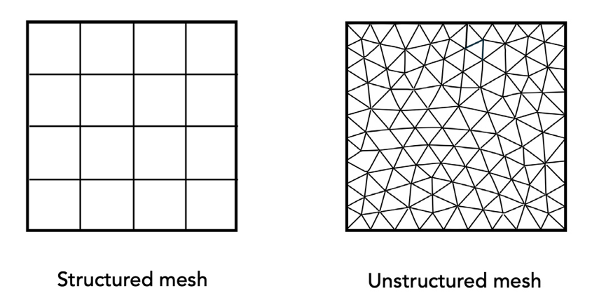
At a high level, meshing is considered either structured or unstructured. Structured meshing is uniform and comprises simple, regular shapes, while unstructured meshing is non-uniform and can contain irregular and varying geometries. FDM requires structured meshes (often called grids), while FEM and FVM can use either depending on the 3D model’s geometry and complexity. The size of mesh elements impacts run time and computational costs, so engineers spend upfront effort refining the mesh to optimize element size and shape.

Meshes can comprise 1D, 2D or 3D elements with boundaries (also called edges) and nodes. 1D elements are lines with two nodes used to model trusses, beams, rods and connections. 2D elements are usually triangles with three nodes or quadrilaterals with four nodes and can be asymmetric or isoparametric. They are used to analyze planar stress and strain for thin shells, plates or membranes. Using 2D elements to estimate thin 3D geometries, such as sheet metal, often saves time.
Tets, hexes and other mesh elements
3D elements are commonly tetrahedra (tet) with four nodes, pyramids with five nodes, triangular prisms with six nodes, hexahedra (hex) with eight nodes or other irregular polyhedrons with varying nodes. They can be asymmetric or isoparametric and include additional midside nodes. In general, hex (also called “brick”) elements can simplify a model, improve accuracy and reduce run time. However, not all geometries are best represented as bricks, so tet elements are used, which often increases the number of elements and, therefore, the number of equations to compute.

Elements can be first-order or second-order, depending on their nodes. First-order elements have nodes only at their corners, while second-order elements have additional midside nodes between their corner nodes. Second-order elements increase accuracy but require more time and computing resources.
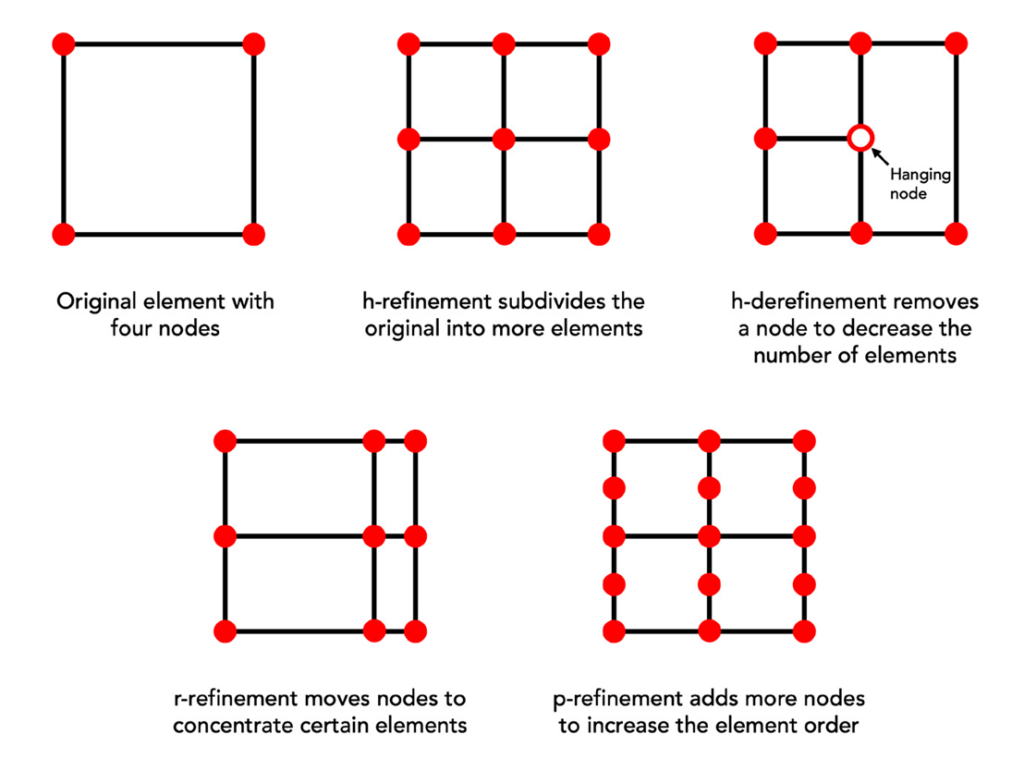
Elements can also have “hanging nodes” that aren’t shared with surrounding elements. Meshes with hanging nodes are considered nonconformal and can occur during mesh adaptation processes. Such processes, typically called adaptive mesh refinement (AMR), add or remove elements and nodes to optimize specific areas of interest. There are three general AMR methods:
- h-refinement: Subdivides elements by adding new nodes within elements to increase mesh resolution (and the number of equations). Contrarily, h-derefinement removes nodes to broaden elements and create a coarser mesh.
- r-refinement: Moves nodes to concentrate resolution in an area of interest without adding or removing nodes or elements.
- p-refinement: Increases the order of the element, from first-order to second-order, for instance.

Meshes can be refined iteratively until they “converge” or get as close as possible to solving the PDEs with algebraic equations and reducing overall error. Simulation software platforms with built-in pre-processors contain meshing tools to help engineers optimize geometries and refine meshes. Third-party meshing software also exists for engineers to import CAD files, create and refine a mesh and export for a solver. However, refining a mesh still takes time and skill and often involves running multiple simulations of different resolutions to compare the results and decide which makes the most sense.
Here are a few things to keep in mind:
- Consider the purpose of the simulation study to determine how much effort you should spend creating and refining the mesh.
- The geometry used in the simulation model should accurately represent the real-world problem.
The mesh directly influences simulation results. Higher-quality meshes yield better results but can consume more pre-processing and solving resources.


