With higher power levels, circuit protection becomes increasingly important; Littelfuse can help.
TTI has sponsored this post.
Recent growth in renewable energy generation has triggered a corresponding demand for battery energy storage systems (BESSs). The energy storage industry is poised to expand dramatically, with the G7 recently setting a 1500GW global energy storage target for 2030. Meanwhile, BloombergNF estimates that investments in energy storage will grow to $103 billion over that period. At the same time, the cost per kilowatt-hour of utility-scale battery systems is likely to drop significantly, making controlling system costs critical.
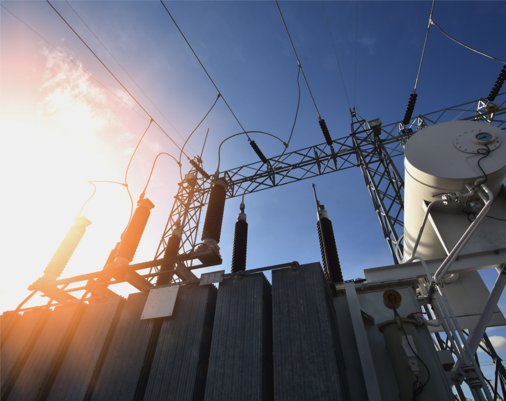
Battery systems aren’t just designed to serve as local power backups, such as the systems used to power critical facilities (including hospitals and data centers) when the normal power source fails. BESSs also offer other benefits and ancillary services, including load-leveling, spinning and regulation reserves, frequency regulation, transmission and distribution deferral. These features maximize BESSs as a valued asset to utilities.
Today’s BESSs are increasingly designed to feed local micro-grids to supply power to small areas when demand rises. They store electrical energy produced by solar or wind power generators, then inject that energy back into the grid when needed.
As the power density of modern lithium-ion batteries grows, BESS integrators are striving to offer their customers more power in a smaller footprint. However, with higher power levels, circuit protection becomes increasingly important.
BESS circuit protection
Renewable energy providers are incorporating new generations of high-efficiency power semiconductor devices into their systems to control power in inverters and converters. Because these are sensitive electronic devices, they require robust protection against energy surges. The design of BESSs can still be considered to be in its infancy, given that the technologies that go into them are evolving rapidly. As a result, many of the electrical engineers integrating those solutions are seeking guidance in selecting and implementing appropriate circuit protection strategies.
A comprehensive circuit protection strategy is crucial to meeting BESS integrators’ most critical objectives:
- To prevent costly service interruptions to end-users with critical uptime requirements, such as hospitals, industrial processing plants and data centers. For example, the cost of data center downtime is in the range of $8,000 per minute.
- To prevent revenue losses for renewable energy suppliers.
- To prevent power disruptions to the local area.
- To protect the workers who will install and maintain the BESSs that integrators design.
- To prevent damage to the BESS equipment itself, which would jeopardize the sizable investment that the end-users or renewable energy suppliers have made.
- To provide grid stability via power generation from renewable sources.
Electrical faults within a BESS can pose significant hazards to workers, including the risk of electric shocks, chemical/electrolyte burns, and the release of toxic or explosive gas. The three main areas of concern are protection against electrical overcurrents, ground faults and arc-flash hazards.
Overcurrent protection
Inverter protection is one of the most important facets of BESS circuit protection. Inverters are typically — although not always — located outside of the trailer or other enclosure in which the banks of batteries are housed. A DC/AC inverter converts direct current (DC) output from batteries into a utility frequency alternating current (AC) that can be fed into a commercial electrical grid. However, a BESS also allows storing the DC current generated by renewable energy sources to a bank of batteries. Later, when there’s a demand for that stored power, a DC/AC inverter converts the DC battery power into AC power that can then be exported to the grid.
In order to provide the longest possible battery discharge times, BESS designers are building in large battery banks. Each of those batteries represents an energy source. Any fault in the system can lead to dumping a massive amount of energy all at once — with all the dangers to people and equipment that could pose.
In the 2017 edition of the National Electrical Code (NEC) Article 706 spells out the overcurrent protection requirements for Battery Energy Storage Systems. The code says:
- Disconnecting Means: “A disconnecting means shall be provided at the energy storage system end of the circuit. Fuse disconnecting means or circuit breaker shall be permitted to be used.”
- Direct Current (DC) Rating: “Overcurrent protective devices, either fuse or circuit breakers, used in any DC portion of an ESS shall be listed and for DC and shall have the appropriate voltage, current, and interrupting ratings for the application.” Exception: Where current-limiting overcurrent protection is provided for the DC output circuits of a listed ESS, additional current-limiting overcurrent device shall not be required.
- Location: “Where energy storage system input and output terminals are more than 1.5m (5 ft) from connected equipment, or where the circuits from these terminals pass through a wall or partition, overcurrent protection shall be provided at the ESS.”
- Sizing: “Overcurrent Device Ampere Rating… provided on systems serving the ESS and shall be not less than 125 percent of the maximum current calculated.”
The existence of these Code requirements helps validate the importance of selecting the proper overcurrent protection in the ever-growing market of BESSs.
A wide range of fuses are available to handle a variety of current overload applications. High-speed fuses are the usual choice for these DC ESS applications because they are much smaller, faster and less expensive than DC circuit breakers. The maximum interrupting rating for circuit breakers tops out at about 200,000 to 300,000 amps. In contrast, the latest generation of high-speed fuses (such as Littelfuse PSR Series High-Speed Square-Body Fuses) (Figure 1) can interrupt up to 150 kA of DC current (or 200 kA AC) in a much smaller footprint than a DC circuit breaker.
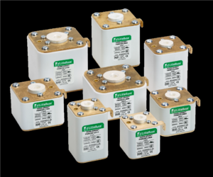
High-speed fuses are designed to operate about 24 times faster than conventional fuses in order to protect sensitive power semiconductor devices (such as diodes, triacs, IGBTs, SCRs, MOSFETs and other solid-state devices) that are built into inverters, UPSs, battery management devices and other systems, by reducing peak let-through current and let-through energy (I2t).
These fuses are also invaluable for protecting a BESS’s DC batteries. Each battery is protected by DC fuses at the positive and negative terminals to isolate the battery during any internal short-circuit condition. DC combiners, where the outputs from multiple battery racks are combined to feed the inverter, are critical locations that are susceptible to high DC overcurrent faults. Typically, at this location, output strings from batteries are protected by DC fuses with the highest possible DC interrupting rating.
Ground faults
A variety of factors can contribute to the development of ground faults. These factors include insulation or component degradation (often as a result of overvoltage or overtemperature), humidity/moisture, rodents, dust accumulation between live parts of the system and human error. Unless an appropriate ground-fault device is used, low-current ground faults can often go unrecognized.
BESSs are typically ungrounded systems. The system may remain in operation after the first ground fault, resulting in higher voltage on the unfaulted bus, with reference to ground, but with no current flow. However, subsequent ground fault on the opposite bus can have catastrophic consequences from both an equipment-protection and worker-safety perspective. A second ground fault on an ungrounded system may constitute a phase-to-phase fault that can result in arcing, fires and severe damage or injuries. Most electrical faults, including arc flashes, begin as ground faults and so detecting these faults early is essential so they can be addressed before serious damage or injury occurs.
For ungrounded BESS systems, designers can choose from three options for ground-fault detection for the DC side:
- Active insulation monitoring. This approach involves injecting a low-level signal that seeks the lowest-resistance path back to the relay through ground. The leakage current returning to the relay is directly proportional to the insulation of the system to ground. This method is attractive, but has some significant challenges, including difficulty in locating the exact fault location, susceptibility to system capacitance and interference of the active signal with other components of the electrical system.
- Passive voltage monitoring with respect to ground. This method does not inject an active signal; instead, it monitors the voltage of each side of the DC bus (or each phase of the AC bus) with respect to ground. The advantage is that there is no active signal to cause any interference, but fault location is a challenge with this method as well.
- Passive current monitoring through use of a ground neutral ground reference. The Littelfuse SE-601 Series DC Ground-Fault Monitor (Figure 2) can provide such a reference. This approach creates a neutral ground point in between the DC bus voltages and looks for leakage current to or from ground. The advantages of this system are that the fault location (positive or negative DC bus) can be determined, there are no active signals to cause interference, and the reference module usually serves to limit fault currents to a safe value. The disadvantage of this method is that a symmetrical fault (a fault of equal resistance to ground on both buses simultaneously) might not be detected.
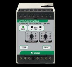
Any current running through to ground requires attention. Sensitive ground fault-relays will pick up leakage currents at 10 mA or even lower. The latest ground-fault relays can pick up levels of fault current as low as 30 milliamps. Typically, a ground reference module is installed between the negative and positive portions of a DC system, the reference model is connected to the relay, and the relay is connected to the ground.
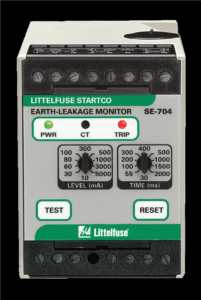
Although most BESSs are ungrounded, grounded BESSs do exist but require different methods of ground-fault detection. Designers need to weigh the relative merits of an AC ground-fault relay vs. an AC insulation monitor. An AC ground-fault relay, such as the SE-704 Earth-Leakage Relay (Figure 3), offers very sensitive ground-fault detection and can be used on systems with significant harmonic content. The output contacts can be connected for use in protective tripping circuits or in alarm indication circuits. The analog output can be used with a PLC or a meter.
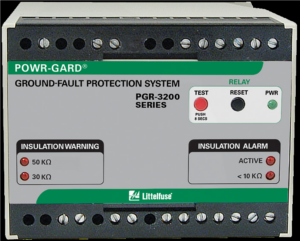
In contrast, an AC insulation monitor such as the PGR-3200 Series Insulation Monitor (Figure 4) which operates on one- or three-phase ungrounded systems up to 6 kV, can also be used on grounded systems to monitor the insulation for damage when the system is de-energized.
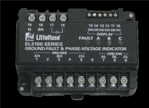
Many designers choose to use a breaker between each battery bank and the combiner box to simplify performing inspection or maintenance on each bank individually. An ungrounded DC ground-fault monitor, such as the Littelfuse SE-601 Series, can be used to monitor the status of the battery banks. It can be used in combination with the EL3100 Ground-Fault and Phase-Voltage Indicator (Figure 5) for 3-phase systems. It meets both the NEC and CE Code requirements for ground detectors for ungrounded AC systems.
Arc-flash protection
According to OSHA, arc-flash events are responsible for approximately 80 percent of electrically related accidents and fatalities among qualified electrical workers. Even when there are no injuries to workers, an arc flash can destroy equipment, requiring costly replacement and system downtime.
The high levels of DC power that feed into inverters from the combined output of the banks of DC batteries creates the potential for arc-flash incidents. When the outputs of multiple daisy-chained batteries are brought together in a combiner box, they can also produce sufficient DC voltage to initiate an arc. Unlike with sinusoidal AC power, where the zero crossing helps AC arcs extinguish themselves, there’s less chance that DC arcs from batteries will be self-extinguishing,
Arc flashes present a number of hazards. The heat can be more intense than the temperature on the surface of the sun, and the accompanying explosion may hurl debris at the speed of a bullet. The threat to both maintenance personnel and nearby equipment is obvious. To mitigate these hazards, arc-flash relays are designed to detect the light from an emerging arc flash and trip an upstream circuit breaker as quickly as possible. For example, the PGR-8800 Series Arc-Flash Relay (Figure 6a) can detect and send a trip signal in less than 1 millisecond, preventing an arc from growing into a potentially catastrophic incident. The trip time for a typical AF0100 Series Arc-Flash Relay (Figure 6b) configuration is less than 5 milliseconds.
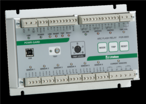
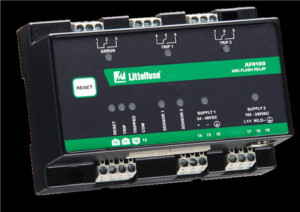
Installing an arc-flash relay system involves placing light sensors around the interior of the enclosure that houses the inverter and the associated bus bars most likely to be the origin of an arc. The power semiconductor device inside the inverter usually fails safe, but it is possible that it or its connectors could fail to ground and cause an arc flash.
Arc-flash considerations for DC and energy storage applications
Allow calculating the arc flash potential for to develop the calculations for arc-flash incident energy on, particularly the development of IEEE 1584 (Guide for Performing Arc-Flash Hazard Calculations). A revision is forthcoming based on further testing with AC systems. However, DC arc flash has been less studied and is less understood. The DC fault currents can be released rapidly on almost all types of BESSs, but those employing lithium-ion batteries can release very large amounts of current very rapidly.
The purpose of arc-flash calculations is to determine the largest possible incident energy. However, a few factors that may not be intuitively obvious can result in higher incident energy levels than would be anticipated if only an overcurrent protective device were used. These factors include:
- Battery age: As batteries age, their internal impedance increases. This can result in lower arc-flash current, which can in fact lead to higher energy because the overcurrent protection device takes longer to operate.
- State of charge: A partially depleted battery bank may not produce full arcing or short-circuit current. Using an arc-flash relay instead of relying on overcurrent protection devices alone for arc-flash protection can help designers realize a consistently low incident energy throughout the lifetime of the BESS.
It’s also important to keep in mind, for incident energy calculations, that battery cabinets tend to direct the energy out of the cabinet door. Large-scale BESS enclosures can expose personnel to even more energy during an arc flash, both by containing the fault and by making it more difficult for workers to self-rescue within a typical two-second window.
The battery banks themselves represent an arc-flash protection challenge in a BESS. An arc flash on one battery bank will be fed from other parallel battery banks. This can be resolved by monitoring the battery bank and disconnecting them from the bus on a fault. At this point, the arc fault is only fed from the faulted bank, reducing its total energy by a factor proportional to the total number of parallel battery banks. The remaining battery banks will continue supplying, or being supplied with, energy. Although disconnecting a faulted bank has a significant impact on operations and reducing incident energy, a fault local to the battery bank is more difficult to address. One option is to provide the means to disconnect/ de-couple sections of the battery bank physically, further reducing the voltage of each remaining section and reducing the hazard and available incident energy while maintenance is being performed.
How Littelfuse can help
Littelfuse is committed to helping BESS integrators ensure that their circuit protection strategy is complete. In some cases, Littelfuse can modify standard circuit protection products to fit an application’s unique requirements. Littelfuse personnel also work with BESS integrators to review their circuit protection plan and ensure it makes sense for the specific application and provides adequate protection for both equipment and workers. By walking integrators through the advantages and costs of the various options available, Littelfuse can help them make informed, cost-effective choices for specific products and locations.
To support the growing BESS market, Littelfuse will provide this expert design assistance at no cost to the system integrator. To request Littelfuse help in creating a comprehensive circuit protection strategy, integrators need only supply some basic information: all voltage levels each circuit will see, the nominal currents each circuit will see in steady state, the available short-circuit current, and the time constants of the application (based on the inductance to resistance ratio).

