A deep dive into the design and optimization of solid flat wire inductors for advanced power electronics.
TTI has sponsored this post.
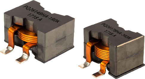
Recently, due to emerging high frequency and wide band gap switches like GaN and SiC, miniaturizing the converter is one of the most important criteria for power electronics engineers. In power electronic converters, magnetic components, like high power inductors, are the key components and correctly designing them has considerable effect on the net efficiency and size of the power converter.
Among high power inductors, there are a wide range of applications where the inductor current has high frequency and very low frequency, or DC components like DC-DC inductors, power factor correction (PFC) inductors, output filter inductors and chokes. In such applications, designing the winding and selecting the wire type is the most challenging part of the design, to comprise and control both low frequency and high frequency conduction losses.
To solve the problem, one solution is using litz wire, however, it has poor porosity or filling-factor of about 40 – 50% for high frequency applications. Hence, compared to solid copper wire, litz wire makes the power inductors bulky with higher direct current resistance (DCR), which adversely affects the power losses for low frequency or DC currents. Due to this fact, in recent power converter applications, new inductor winding structures are proposed based on solid wire and companies like Bourns are manufacturing flat wire inductors for renewable energy applications. However, improper designing of solid wire increases ESR for high frequency applications.
To make an optimal compromise between DCR and ESR at high frequencies, several solutions based on solid copper wire have been proposed in the literature. For example, in, a design procedure for round wire is presented with a single layer winding structure to reduce ESR for high frequencies. However, this winding structure is suitable for toroid shapes, while for the other core geometries such as a P-core geometry, the inductor will become bulky and a major part of the core’s window area remains empty. Another alternative is multi-layer foil windings; however, this wire type is suitable for medium frequency transformers with interleaved windings. For inductors and other multi-layer windings, foil wire presents higher losses due to the proximity effect between the layers.
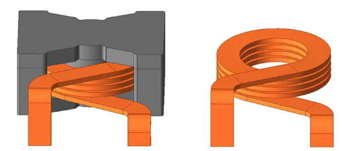
Among different solid wire types, flat spiral and helix shapes present superior performance, while they have better manufacturability in printed circuit boards (PCBs) and a reduced size of magnetic components. Spiral shapes have proximity effect issues and are more suitable for high frequency planar transformers. Solid flat wire winding presents better thermal conductivity and DCR; however, more work is needed to have accurate and simple models suitable for design optimization algorithms. Fig. 1 shows a power inductor based on a helical flat wire coil.
This study accurately models and formulates inductor DCR and ESR based on solid flat wire. Then, the performance of this structure is compared to solid round wire with equivalent wire gauge and window size, using 2D FEM simulations. In this research, the formulation and simulations are considered for inductors with cylindrical geometries such as PQ and P-core types, which are considered the most frequently used core geometries with higher power density and fewer leakage flux problems.
The main parameters of the solid flat wire inductor are defined based on equivalent winding parameters with multi-filar solid round wire. Then, the solid flat wire formulations for DCR and ESR are derived. Next, 2D FEM simulations are presented and the two winding structures are compared. Based on FEM simulations, the ESR formula is further modified, and conduction losses of the inductor are formulated for DC-DC converters. Finally, experimental results for a laboratory sample with flat wire are presented.
Modeling of the Flat Wire Inductor
Without loss of generality, the main parameters of the flat wire coil are formulated based on an equivalent inductor with solid round wire, which has a similar winding area, i.e., equal winding internal radius, rw, radial thickness, Dw and height, Hw, as shown in Fig. 2. Furthermore, it is assumed that round solid wire has a non-twisted bundle containing m strands, or m-filar, with diameter of ds. In this paper, it is assumed that solid round wire has few non-twisted strands. Obviously, a higher number of twisted strands improves ESR, however, in this case the wire is classified as litz wire and not solid wire.
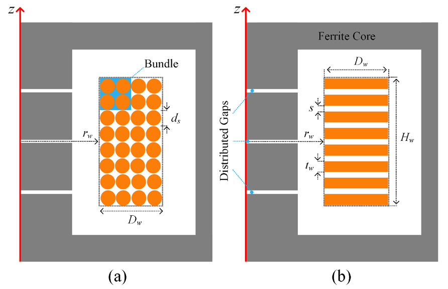
Regarding Fig. 2 and the round wire parameters, the flat wire thickness, tw, can be calculated by:

Assuming a unit porosity factor for the round wire inductor, i.e., negligible space between round wires, the filling-factor of copper cross section area would be equal to π/4. Then, assuming a similar copper filling-factor for the flat wire winding, the space between turns, s, is derived by:

Considering the cylindrical symmetry shown in Fig. 2, the conductance of a differential ring, dG, with a distance of r from the z-axis and differential cross section area of twdr is:

Here, σ = 5.8 × 10⁷ S/m is the conductivity of copper. Each turn can be considered as an equipotential surface and the total conductance of one turn, G, can be derived by:

Using (4), the DCR of the flat wire winding, Rdc, with N number of turns, is derived from:
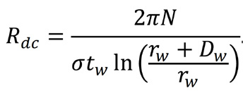
It is worth noting that the helical effect on the length of the winding is neglected in (5), since the pitch of the coil is much lower than the coil’s mean diameter, i.e. (tw+s) << (2 rw+Dw).
To calculate ESR, Rac, under sinusoidal alternating currents (AC), several analytical solutions have been developed in literature. However, they are mainly developed for solid round wire. For rectangular conductors, recent analytical formulations are developed only for a single solid flat wire in 2D x-y plane. Furthermore, according to the analytical solutions, the formulas are accurate when the thickness of the conductor is less than double the skin depth, δ, which is defined by (6).
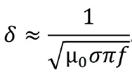
Here, μ0 and f are the vacuum permeability and frequency of the sinusoidal current, respectively. For high power inductors, the flat wire thickness, tw, is typically selected high enough to carry high currents and for high frequency DC-DC converters, typically tw ≥ 2δ. Hence, in this study, analytical formulations will not be accurate enough.
Neglecting the fringing effects of the distributed air gaps, shown in Fig. 2(b), to calculate Rac, first it is assumed that the inductor current effectively passes through rings with radius of rw and thickness of skin depth,δ, by assuming tw << Dw. Hence, the ESR, Rac, as a function of f, is calculated in (7), by assuming that δ is much smaller than Dw and tw ≥ δ.

However, rings-model is affected by edge-effects of the first and last turns and the space between turns, s. Using FEM simulations, it is shown that for a specific N and tw, this model can be corrected by a fix correction factor of kw, as included in (7) and the presented formulation accurately derives Rac in a wide range of operating frequencies defined by:

Here, fmin is the minimum frequency at which the model is accurate and is defined by tw ≥ δ criterion using (6). Next, FEM simulations are presented to compare the two different solid wires and Rac model assumed in (7).
2D FEM Simulations and Modified ESR Formula
To calculate Rac, 2D Poisson equation for the magnetic potential, A, under steady-state condition, is solved in (9), neglecting the displacement currents:

Where, Js, Jind and Jt are the peak density values of source current, induced current and total current, respectively. For operating frequency of f, Jind relates to A, as presented in (10), and the relation between the inductor’s peak current, IL, and Js are obtained by (11), as follows:


In (11), the integral is calculated on a surface area of one turn. By solving A, Rac can be achieved by calculating ohmic loss in all cylindrical coordinate and dividing the calculated loss by the squared value of the inductor current, as follows:

To compare the two solid copper wires, first it is assumed that the power inductor is implemented with solid round wire with N = 8, rw = 12.5 mm, and m = 4 with ds = 1.50 mm. In this design, 20 μm is considered as the insulator thickness between conductors, which has negligible effect on the final dimensions and DCR.
Hence, Dw and Hw are calculated at approximately 6 and 12 mm, respectively. On the other side, according to Fig. 2 and using (1) and (2), tw and s are calculated at 1.178 and 0.322 mm, respectively. The two inductors are implemented by a PQ50 core with a height of 33.0 mm. For the sake of simplicity, in the following simulations, the core is considered linear and lossless with a relative permeability, μr, of 2400. To have a negligible fringing effect, three 0.25 mm gaps are considered at the center leg of the core.
To calculate the DCR of the two inductors, two FEM magnetostatic simulations have been done for the two inductors. The DCR for the flat wire and round wire inductors are derived as 1.8766 and 1.9590 mΩ, respectively, meaning that the inductor with solid flat wire has a 4.2% lower DCR. On the other side and using (5), the DCR is calculated at 1.8770 mΩ, which is very close to the magnetostatic simulation result, at approximately a 0.02% margin of error.
Fig. 3 shows a 2D Eddy-current FEM simulation and the mesh plot for the solid flat wire inductor model with f = 100 kHz and an AC peak current of IL = 5 A. Based on 2D eddy-current FEM simulations, the inductor value is calculated at approximately 34.8 μH. By using (12) and post-processing the magnetic vector potential, A, Rac is derived at approximately 33.3 mΩ. As seen in Fig. 3(b), except for the edge effects, the current mainly passes through rings.
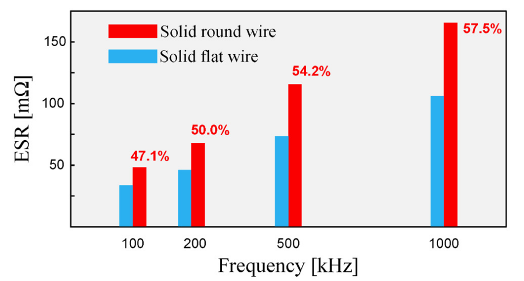
Using similar FEM simulations, ESR for the solid round wire inductor is calculated at 49.0 mΩ, i.e., 47.1% higher than the flat wire inductor. For the round wire design, there are two main reasons behind its higher ESR. The first reason is that the coil has two layers and the number of layers adversely affects the winding’s ESR. The second reason is the fact that here the bundle is not twisted, and the current is not uniformly distributed between the four strands.
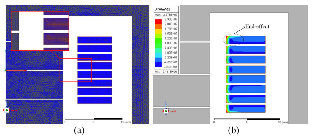
Fig. 4 compares the ESR of the two designs for different frequencies up to 1 MHz and shows that the solid flat wire is significantly better, especially at higher frequencies, while the proximity effect between the two layers of the round wire design increases significantly. It is worth noting that for solid wire design with fewer parallel branches, m < 4, the ESR will be even higher which confirms the superiority of solid flat wire.
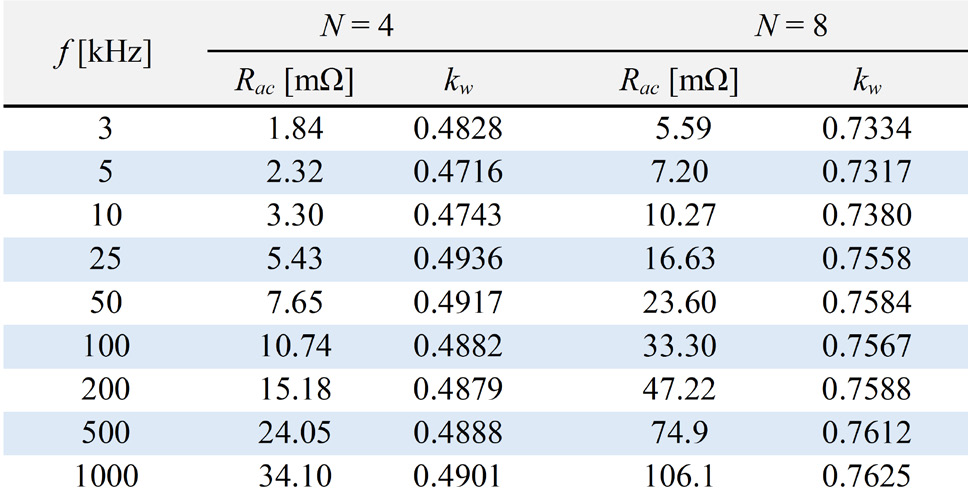
To show the proposed assumptions described in (7), FEM simulations under different operating frequencies are done for two inductors manufactured with solid flat wires. Table 1 presents the calculated Rac for the two inductors with N = 4 and 8, and similar tw = 1.178 mm and s = 0.322 mm. Using (8), fmin is calculated at approximately 3 kHz, hence Table 1 presents the results for frequencies from 3 kHz up to 1 MHz. To calculate kw, first, Rac is calculated by (12) using FEM simulations. Then, using (7), the physical parameters of the winding and the known Rac, kw can be calculated for each FEM simulation, as included in Table 1.
According to Table 1, kw for the two designs is almost constant with less than a 4.2% variation from 3 kHz up to 1 MHz. Similar FEM simulations have been done for Dw = 9.0 mm and f = 100 kHz, and kw values for N = 4 and 8 are derived at approximately 0.4768 and 0.7510, respectively which are very close to the results presented in Table 1. This means that for tw << Dw, which typically occurs for high power inductors, kw is approximately independent of Dw. Hence, assuming the constant filling-factor of π/4 defined in (2), kw only depends on the number of turns and wire thickness. Typically, inductors based on flat wire are made with few turns, and it is feasible to calculate a table-function of kw (N, tw) for calculating ESR in a wide range of operating frequencies, which is suitable for design optimization algorithms.
As concluded from the above-mentioned analysis and simulations, equation (7) can model Rac in a wide range of operating frequencies. Hence, it is possible to formulate the conduction losses of flat wire inductors for DC-DC converters as follows. As an example, for a buck converter with a regulated output voltage of VO and load current of IO, the maximum current ripple occurs at a duty cycle of 50%.
In this condition, the voltage of the inductor, L, is like a square wave voltage source with an amplitude of VO and switching frequency of fs. Using the Fourier series, the inductor voltage, vL(t), and its hth current harmonic amplitude, Ih, can be formulated by:


Hence, using (7) and (14), the maximum AC conduction losses, Pac, are derived by:
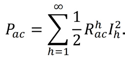
Here Rach calculates the ESR for hth harmonics, i.e., for f = hfs, by using (7). In (14), the current amplitude significantly reduces for high order harmonics, hence, the AC conduction losses can be well approximated up to the 9th harmonic, as follows:

Moreover, it is assumed that the self-resonant frequency of the inductor is higher than the 9th harmonic and the inductance value of L can be considered constant in the above-mentioned analysis. DC conduction loss, Pdc, is calculated by (17), where Rdc is the DCR of the inductor calculated by (5):

Finally, a simulation has been done for a buck converter with fs = 100 kHz, VO = 100 V and IO = 30 A based on the flat wire inductor the number of turns = 8 and L ≈ 34.8 μH, as presented in Table 1. It is assumed that the output voltage has negligible ripple, and the duty cycle of the buck converter is 50%. Using (16) and (17), Pac and Pdc are calculated at approximately 0.558 W and 1.689 W, respectively. The calculated values have been verified by doing a transient FEM simulation with a time step of 50 ns. According to the FEM results, the total conduction loss, Pac plus Pdc, are calculated at approximately 2.402 W which has at approximately 5.5% deviation from analytical calculations.
Experimental Results
To verify the analytical formulations, a 5.6 μH, 80 A power inductor is implemented with N = 4, tw = 2.0 mm, Dw = 9.5 mm, s ≈ 0.6 mm and rw = 11.0 mm, as shown in Fig. 5(a).
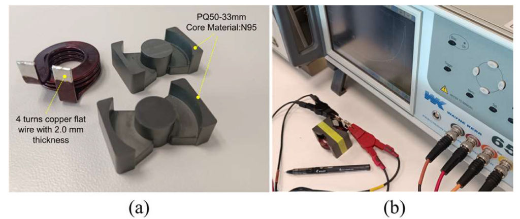
To have 5.6 μH inductance, three 0.4 mm air gaps are required at the middle leg of the core, to reduce the fringing effects. However, for the sake of simplicity, only one 0.4 mm gap is considered for ESR measurements. The core is PQ50 with N95 ferrite material and a height of 33 mm. According to (5), DCR is calculated at approximately 387 μΩ for this inductor, including 4.5 cm extra length of wire for the end terminals. To measure DCR of the inductor, a 25 A DC current was applied to the inductor and voltage of approximately 10.0 mV was measured at room temperature, which means that the DCR is measured at approximately 400 μΩ, i.e., a 3.35% margin of error from theoretical calculations.
For this inductor and using FEM simulations, the correction factor, kw, for the mentioned N and tw is calculated at approximately 0.9764, with less than 4.0% deviation from fmin ≈ 1 kHz, defined by (8), up to 1.0 MHz. To measure the ESR, it is worth noting that the core also reflects extra ESR in the inductor coil, due to the eddy-current and hysteresis losses in the core.
To exclude the reflected resistance from the core, the ESR of an inductor made by 1050×0.05 mm litz wire, N = 4 and the same core is measured as the reference measurement. Regarding FEM simulations, AC and DC resistances of the litz wire are very close to each other for operating frequencies under 100 kHz, with less than a 2% change. Hence the measured ESR of the reference inductor with the litz wire is approximately equal to its DCR plus the extra ESR reflected from the core. Using a WYNE KERR 6500B impedance analyzer and f = 100 kHz, the total ESR, including the core effects, for the flat wire inductor and the reference inductor with litz wire are measured about 14.6 and 6.4 mΩ, respectively. Moreover, the DCR of the reference inductor is measured at approximately 4.2 mΩ. Hence, the ESR of the flat wire winding at 100 kHz is measured at approximately 12.4 mΩ, which has about a 12 % error from (7) with the mentioned kw.
Conclusion
This article presents modeling and analysis for high power inductors manufactured with solid flat wire and develops formulations to accurately calculate their AC and DC resistances. The simulations and experimental results show that the flat wire type presents superior DCR and ESR, compared to a non-twisted solid round wire, using an equivalent wire gauge and window area. Furthermore, by using FEM simulations, a correction factor has been defined to accurately calculate ESR for different turn numbers and wire thicknesses, with less than a 5% error, which is suitable for design algorithms. The model has been verified by experimental results and further FEM simulations using different wire sizes and number of turns in a wide range of operating frequencies. Furthermore, based on the ESR formula, the maximum AC conduction loss of a flat wire inductor has been formulated for buck converters.
To learn more, visit TTI Inc.

