A primer for engineers on simulating thermal phenomena in 3D printing.
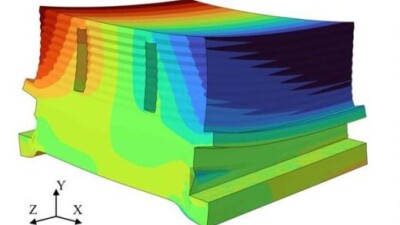
Most additive manufacturing (AM) processes involve using thermal energy to fuse feedstocks into 3D printed parts, layer by layer. While this approach allows for more complex internal geometries than traditional processes, such as casting, molding or machining, it can also introduce anisotropic material properties and residual stresses as a result of heterogenous heating and cooling in 3D printed parts, which can cause directional solidification or grain growth in the material, particularly in metal AM processes.
This in turn can make the mechanical properties of 3D printed parts less consistent, as well as affecting print speeds – due to the need to account for temperature variations across the part – and reducing surface quality and dimensional accuracy.
This is why it’s crucial for engineers to understand an additive part’s thermal history, since that determines its microstructure, its mechanical properties and its final dimensions. Thermal simulations can help optimize these key performance indicators (KPIs) by modeling the thermal history without the need to actually 3D print experimental parts.
What’s involved in thermal simulation for additive manufacturing?
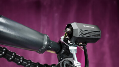
While the relevant process variables will obviously depend on the particular additive manufacturing process being simulated, in the context of laser powder bed fusion (L-PBF), for example, these include:
- Laser power
- Laser spot diameter
- Laser offset
- Scanner head speed
- Layer thickness
In this context, a part’s temperature history affects the melt pool dimensions, defect formation, solidification conditions, remelting cycles and residual stress. What makes AM simulation even more challenging is the fact that it requires analyses of temperature changes at sub-nanosecond timescales, which are orders of magnitude shorter than the entire build duration. For this reason, thermal simulations of L-PBF builds can take hours or even days to complete.
How do materials affect thermal simulations for AM?
Next to the specific additive manufacturing process, the materials being 3D printed will have the biggest impact on thermal simulation for AM.
For metals used in L-PBF or direct energy deposition (DED), their high thermal conductivity allows for rapid heat dissipation, which can lead to thermal gradients across the part and cause residual stress that can result in warping or distortion. Metals also undergo solid-state phase changes during cooling, such as martensitic transformations in stainless steel. Beyond these general considerations, there are also alloy-specific considerations for thermal simulations of metal AM: for example, titanium alloys are highly reactive and oxidize easily and so require controlled atmospheres while aluminum is more prone to solidification cracking.
In contrast, polymers used in fused deposition modeling (FDM) or selective laser sintering (SLS) exhibit low thermal conductivity, resulting in slower cooling rates and a greater propensity for residual thermal stresses or warping. This is especially problematic in semi-crystalline polymers, such as nylon, in which slower cooling can result in the formation of crystals that impact mechanical strength. Polymer materials are also at risk of thermal degradation due to excessive heat, which can cause brittleness or off-gassing. Finally, simulations involving 3D printing with thermosets (as opposed to thermoplastics) must also account for the effects of the curing process.
How do you do thermal simulation for 3D printing?
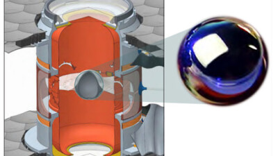
Thermal simulations often use numerical methods due to the complexity of the phenomena they’re modeling – for example, using finite element analysis for heat transfer during metal deposition.
However, the speed of many 3D printing processes, combined with the complexity of the spatial and temporal dynamic thermomechanical phenomena makes the computational costs of numerical modeling for AM particularly high, especially when trying to simulate the entire thermal history of a part. For this reason, FEA is often too computationally complex and time intensive to be practically useful during manufacturing. Reduced-order models (ROMs) and hybrid techniques that combine a finite element method (FEM) with other methods are emerging to address this computational cost issue, but at the time of writing these are still in relatively early stages of development.
Ultimately, additive manufacturing simulation can be understood as a multiscale problem in both time and space. From this perspective, engineers can control the scale of a simulation and the solution fidelity by choosing appropriate time incrementations and mesh sizes.
Considered on a spectrum, process-level simulations with small time increments and fine meshes are high fidelity, versus part-level simulations with averaged time sequences of events and coarser meshes, which are low fidelity. In the former case, the simulations are intended to capture the rapidly changing temperatures and high-temperature gradients found within and near zones where active melting or fusion occurs. In the latter, the temperature results do not usually contain an accurate thermal history, though a heat transfer analysis can still capture changes away from the active zones, so long as the thermal energy balance of processive heating and cooling has been modelled correctly.
Modelling thermal transport phenomena in AM processes is complex, needing to account for moving heat sources, phase changes and various mass and heat transfer phenomenon. However, when done correctly, thermal simulations can enable design and manufacturing engineers to make design changes to ensure more homogenous cooling, introduce supports to minimize distortions or change process parameters to reduce the risk of defects.


