CAD standards are important to ensure that information is read and interpreted correctly by any party.
Following a CAD standard ensures that designs are clear, correct and understandable by all parties viewing them. If drawings always look the same, it makes it easier to read and understand the information.
To make this easier for users, AutoCAD has a set of CAD Standards tools that help maintain consistency and adherence to company (or industry-specific) standards. Here’s how to use them.
Building your AutoCAD standard

Step one is building the standard. The CAD Standards tools rely on drawing standard files (.dws). These standards files are a special type of drawing with all the settings and styles of drawings minus the geometry.
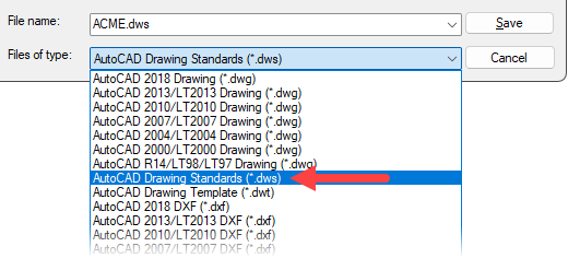
As .dws files are drawings, you can start from scratch or save an existing drawing. You have control over what the standards define. Create standards for project or customer requirements, company guidelines or to match industry standards. AutoCAD checks layers, linetypes, and styles for dimensions, multileaders and text.
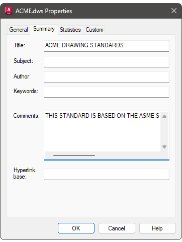
The drawing properties title and comments become the standards description and are viewable when attaching it to a drawing.
Configuring standards in AutoCAD
Configure Standards lets you associate drawing standards files with the current drawing. The .dws file acts as the reference for all standards checks and corrections.
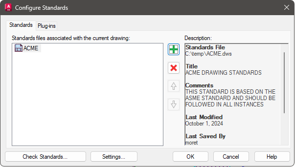
The description is information about the standards currently selected. This description is the title and summary set in the drawing properties of the standards file.
Use Remove (the X) to dissociate the file. This does not delete the file but removes it from the drawing.
As you can associate multiple standards, use the arrows to change the order. AutoCAD checks standards starting with the first in the list and works its way to the last. If the same style or layer exists in different standards, AutoCAD uses the settings of the first found.
AutoCAD adds a standards plugin for each standard object it checks. From the Plug-ins tab, you can turn off object types you do not want to check for in the drawing.
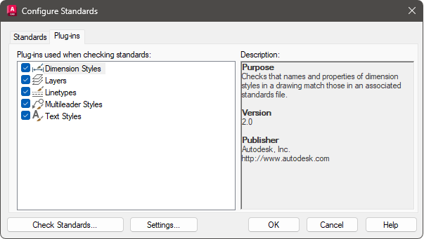
Use the settings to manage options for notifications and checking standards.
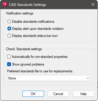
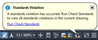
Notifications can be turned on or off or be set to display as an icon in the status bar. When set to Display Alert upon Standards Violation, AutoCAD shows an alert bubble as a standards violation occurs. As an icon, no notification bubbles pop up, but an icon appears in the status bar.
Enable the automatically fix feature for AutoCAD to correct non-standard properties without prompting. AutoCAD only fixes non-standard objects when the style or layer name matches one in the standard but the properties differ.
The standard used to automatically fix non-standard properties defaults to the first standard in the list. Alternatively, select the standard for AutoCAD to use from the Preferred standards list.
Checking standards in AutoCAD
Select Check Standards to compare the current drawing against the attached standards (.dws). You can also start it from the standards violation bubble notification.
The process flags property discrepancies found in layers, styles and linetypes against the standards. With each violation, you can fix it, mark it as ignored or select next to skip it and move on.
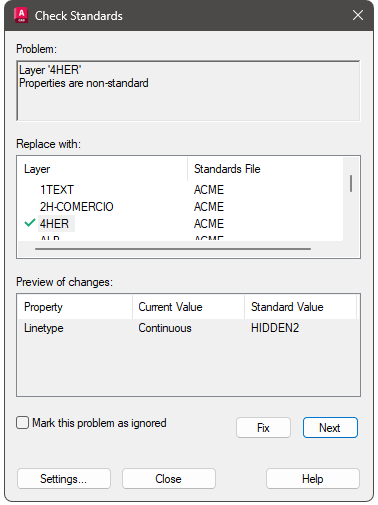
The problem describes the nonstandard object or property discrepancy. With non-standard objects the Fix button stays unavailable until you select a fix. To resolve the problem, select the replacement from the Replace With list and click Fix.
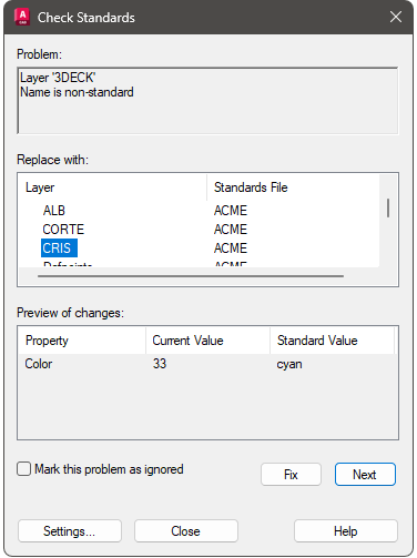
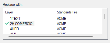
AutoCAD lists all possible replacements for the current violation; the recommended one (if there is one) is preceded by a check mark. The preview shows the properties of the non-standard object changing with the selected Replace With.
Select Mark This Problem as Ignored to flag the violation as confirmed. Use this when you accept the violation to not make any changes. This tags the violation with your name so others who may use the drawing do not fix the issue.
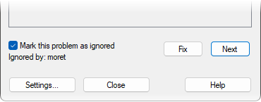
If the Show Ignored Problems option is turned off in the CAD Standards Settings, ignored problems are not displayed the next time the drawing is checked.
Select Settings to access the CAD Standards Settings dialog.
Layer Translator in AutoCAD CAD Standards
The Layer Translator transcribes the drawings layers to another layer set. This is useful when collaborating with others or transitioning to different standards.
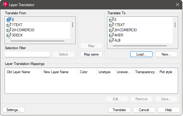
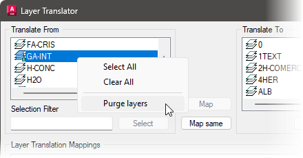
The Translate From section lists the current drawings layers, those to be translated. The icons proceeding the layer name differ between referenced and unreferenced layers. You can delete unreferenced layers (as they are not used) by right-clicking the layer and selecting purge.
Use Load to add the destination layer scheme. You can use a drawing, drawing template or standards file.
You can load layers from more than one file. If you load a file that contains layers of the same name as layers already loaded, the original layers are retained and the duplicate layers are ignored.
Select New to define a new layer. This layer appears in the Translate To list for translation. If you select a Translate To layer before choosing New, the selected layers properties are used as defaults for the new layer. You cannot create a new layer with the same name as an existing layer.
Typically, you start with Map Same. This matches the same named layers in both lists. The drawings layers properties change to match those of the matched layers in the Translate To list.
In the Translate From section select a layer or layers you want to translate. Then select the desired destination layer from the Translate To section. Pick map to perform the translation.
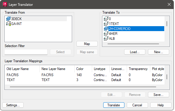
The Layer Translation Mappings section lists each layer to be translated and the properties to which the layer will be converted. You can select layers in this list and edit their properties using Edit.
With drawings with many layers, consider using the Selection Filter to quickly select layers based on wildcard searches.
Use Save to capture the current layer translation mappings to a file for later use. Select Translate to start the translation process.
Batch Standards Checker in AutoCAD
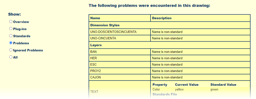
With the standalone Batch Standards Checker you can check multiple drawings for standards violations. This tool does not fix the violations but creates an HTML report summarizing the found issues.
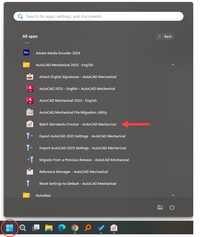
Find this tool in the Start Menu in the AutoCAD folder. It is included with all flavours of AutoCAD, including AutoCAD Mechanical (shown in the image).
To run an audit, you require a standards check (CHX) file. This check file sets up the scan. Once created, you can reuse it in future scans.
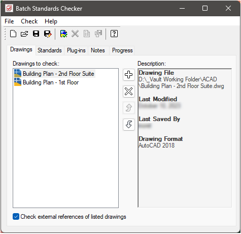
To create the check file, start by selecting New. Then, from the Drawings tab, select the plus icon to browse for and select the drawings you want to check. You can repeat this process to select drawings from different folders.
AutoCAD scans the drawings in the listed order. Use Move Up and Move Down to reorder the drawings. Use the X to remove selected drawings.
Enable Check external references of listed drawings to include found XRefs and scan them for violations.
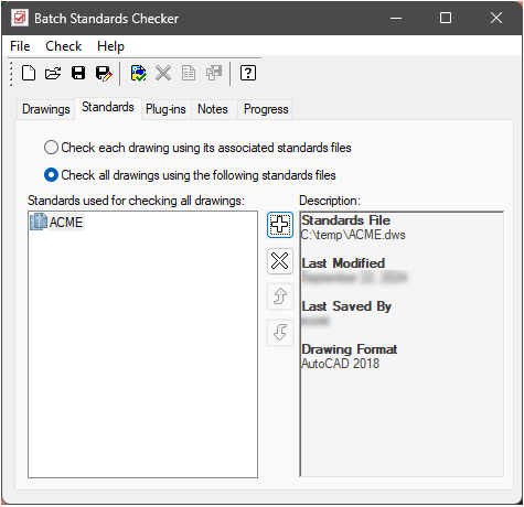
By default, the Batch Standards Checker checks each drawing against its associated standards files. Use the Standards tab to change this default and add standards files. The checker then uses the assigned standards, ignoring all associated standards contained within the drawings. You also want to do this when there are no standards associated with the drawings.
When adding multiple standards, the order sets the precedence, with the top one taking the highest priority. Use Move Up and Move Down to rearrange the order.
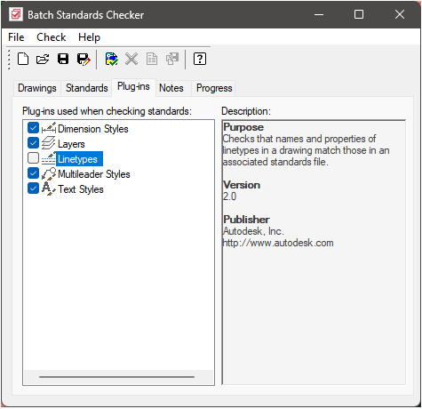
With the Plug-ins tab, you can disable standards from being checked. For example, turn off Linetypes so the scan does not look for linetype violations.
Use the Notes tab to include comments in the report.
From the Batch Standards Checker toolbar, click Save to save the current standards check file or Save As to create a new check file.
With the check configured, select Start Check from the tool. This starts the scan against the loaded drawings. The Progress tab shows summary information about the scan status.
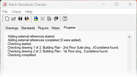
After the batch standards audit is complete, you can view an HTML report with details of the audit. You can also create notes that are included in the HTML report. This report can be exported and printed. In a collaborative environment, you can distribute the report to drafters so that they can fix any problems with their sections.
In summary, the standards tools within AutoCAD offer a mechanism for enforcing consistency, improving collaboration and enhancing the overall quality of your CAD drawings.
