Beginner or expert, every Inventor user should know these simple time savers for sketching, modeling, assemblies and more.
Whether you’ve just downloaded Autodesk Inventor or are a longtime user of the CAD software, there’s always something you can do to make your workflow just a little more efficient. Here are 29 tips for sketches, models, assemblies, drawings and more that will save time for all Inventor users.
Sketching tips for Autodesk Inventor
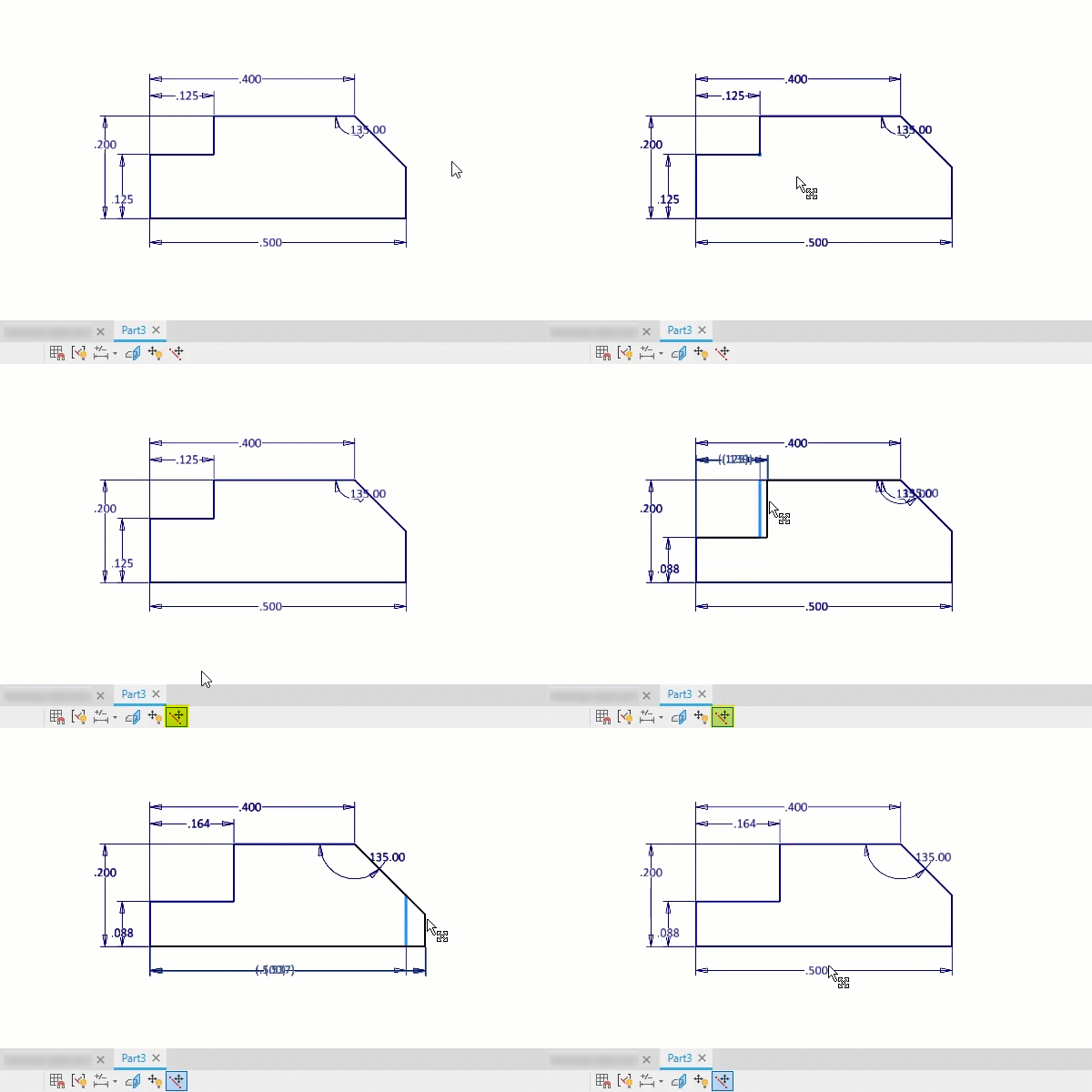
Get to the point of horizontal and vertical constraints
Applying Horizontal or Vertical constraints to a line makes it parallel to the X or Y axis of the current coordinate system. However, did you know you also align points horizontally or vertically?
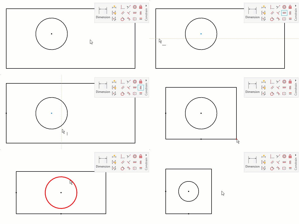
Inferred constraints
As you sketch, Inventor predicts constraints based on the geometry and your cursor position. Pay attention to these inferences—applying constraints in real-time speeds workflows since you won’t need to apply constraints after.

Relax mode
You have done your work and fully constrained the sketch—good job! But now you realize you need to make dramatic changes. By enabling Relax Mode, you can change geometry as if the constraints do not exist. Inventor reapplies constraints as you make changes, as it can.
Copy and paste AutoCAD geometry
Why redo when you can reuse? You can copy geometry from AutoCAD and paste it directly into your Inventor sketch.
Once pasted, add dimensions and constraints as if the geometry originated in Inventor. Or use Auto Dimensioning to apply the easy constraints like horizontal, vertical, perpendicular and parallel.
Make project geometry work for you
Projecting geometry from one part onto another is a powerful tool. This sets up cross-parametric relationships between parts so that as one part changes the other updates automatically to match.
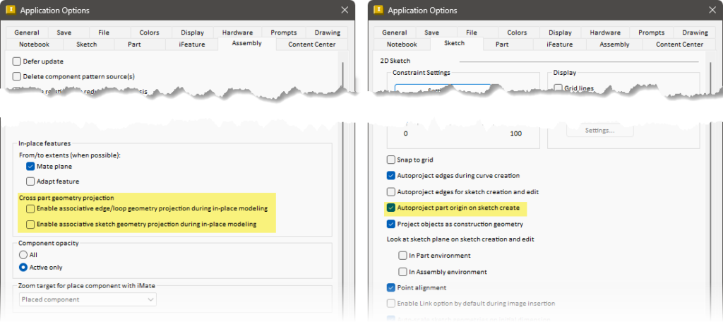
However, you may not always want this associativity to occur. You can override this behaviour by holding Ctrl. The geometry then projects (copies) in place, but not associative to the original. Inventor applies fixed constraints to keep it in place.
You can also flip the default behaviour in the Application Options, turning off cross part geometry projection. Now you need to hold Ctrl to build the adaptive relationship.
And while you are adjusting Application Options, make sure to enable Autoproject part origin on sketch create. This automatically projects the model’s origin point as reference geometry, which is a must.
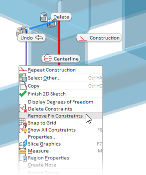
As a bonus tip, you can quickly remove constraints by selecting the geometry, right-clicking, and selecting Remove Fix Constraints. This will remove the fix constraints on the projected objects, freeing the geometry.
Press and hold
When sketching lines, press, hold and drag off any point to generate a tangent arc from that point. If you drag away from a line or arc, Inventor creates perpendicular lines. If you drag tangent-like from an arc or circle, you create a tangent line. If you continue to hold as you create the line, you can snap tangent at the other end as well.

Splitting the difference
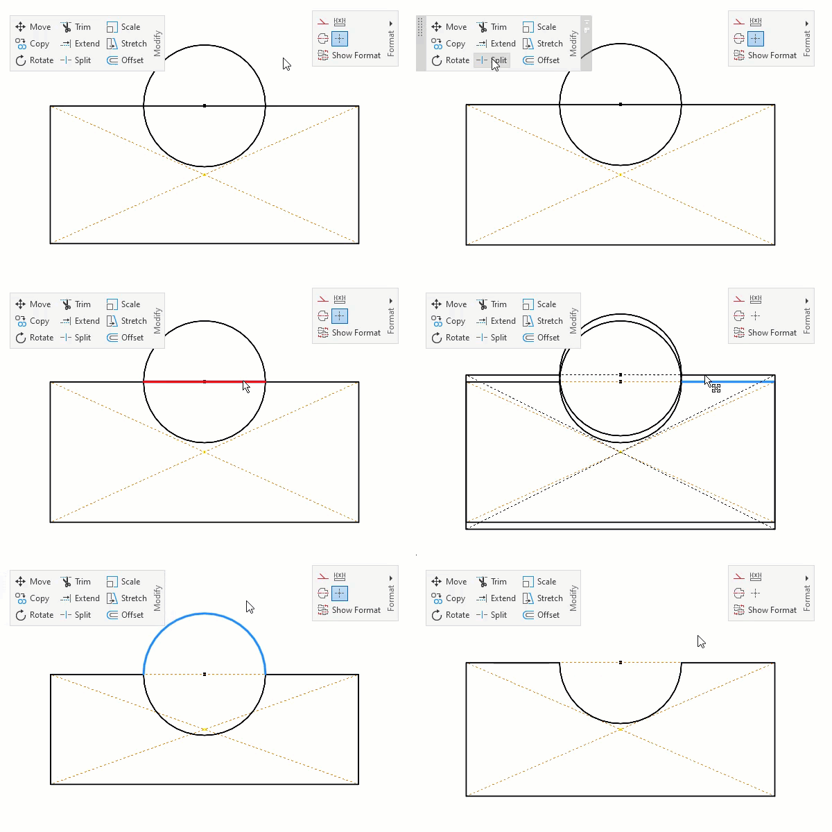
When needing to remove objects, consider using Split instead to divide entities into multiple objects. This is a great method to generate construction geometry, keeping the constraints, as opposed to removing objects and losing the constraints.
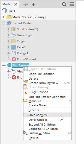
Export face and export flat pattern
Any face or flat pattern can be exported to DWG or DXF, avoiding the need for a drawing.
UI tips for Autodesk Inventor
Be just like AutoCAD
There are many things that Inventor mimics from AutoCAD—in a good way. These provide little time savers. For example, the Spacebar repeats the last command, a simple but versatile shortcut.
What the F Key
Use the F keys for quick access to view manipulation features. The feature stays active as you hold the key and turns off as you let the key go.
F2 = pan
F3 = zoom
F4 = orbit
F5 = previous view
F6 = home
Master the marking menu
The marking menu is an efficient way to access commands quickly. When right-clicking in the graphics window Inventor provides a radial menu of commonly used tools. This menu is context sensitive to the environment and what you have selected.
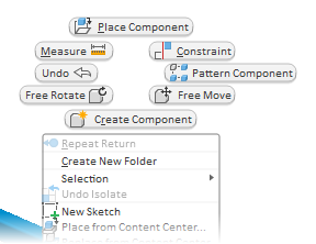
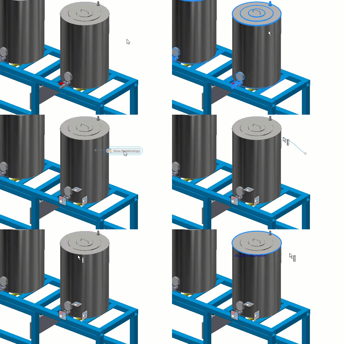
It is also gesture based. If you right-click and drag in the direction of the radial location, it starts the command.
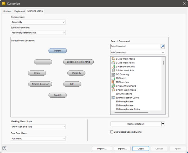
Bonus tip: You can customize the marking menu to your liking to access your frequently used tools.
Getting help
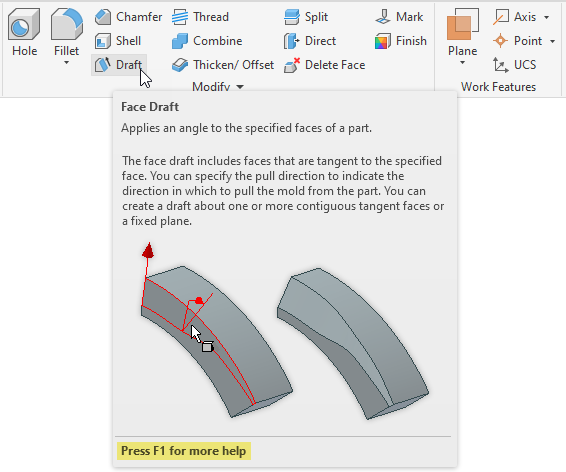
If you are just starting out or wanting help with a rarely used tool, hold the cursor over the command in the ribbon. When the tooltip appears, press F1 to launch the help and navigate right to the help section for that command.
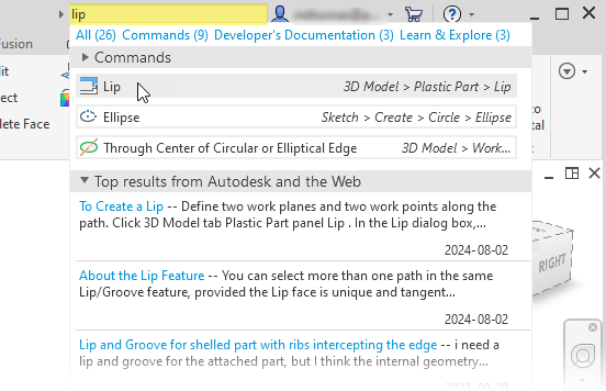
If you don’t know where to find the command in the interface, use the search bar to look it up. You can start the command directly from the list, and Inventor highlights its location in the ribbon.
Modeling tips for Autodesk Inventor
Select other
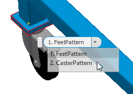
It is no fun when something is blocking what you want to see in Inventor. Instead of turning off the blocking object, pause and wait for Inventor to show Select Other. With this, you can cycle through all the objects behind your cursor, settling on the one you are after.
You can cycle by rolling the mouse wheel over the glyph or by selecting from the drop-down.
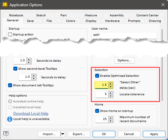
In the Application Options, you can manage the time delay before Select Other appears.
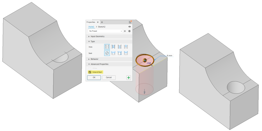
Extended holes
Extended Start, an advanced hole property, extends the start of the hole until there is no intersection with the target body. This is much quicker than adding subsequent features to remove the unwanted fragments.
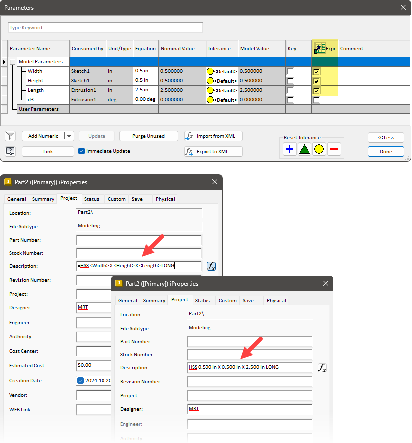
iProperties+
Parameters, once exported, can be used with the file’s iProperties. You can mix text and parameters to build the expression. Use this to build smart iProperties, ones that update as the parameters change. Inventor evaluates the expression when clicking Apply or pressing Enter.
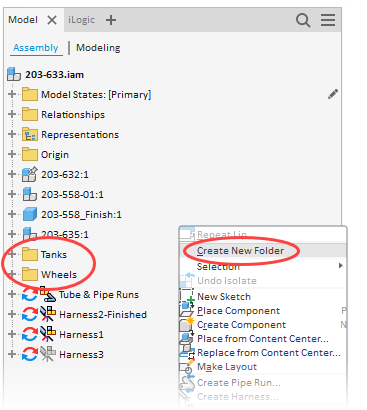
Manage your browser
The browser is the hub for your model’s features and parts.
Make it cleaner with folders, managing how the information is presented. By organizing components into folders, you can reduce clutter and make finding parts easier. You can also perform functions on the folder that apply to everything contained within it.
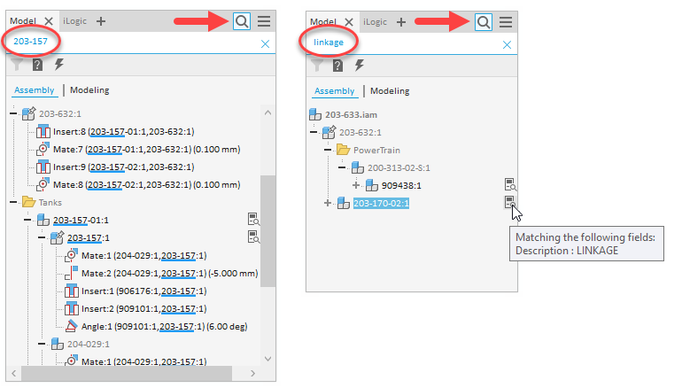
Can’t find something? Use the search to quickly find features and components based on names and iProperty information.
Declutter the browser even more by hiding the UCS, work features, notes, documents and warnings.
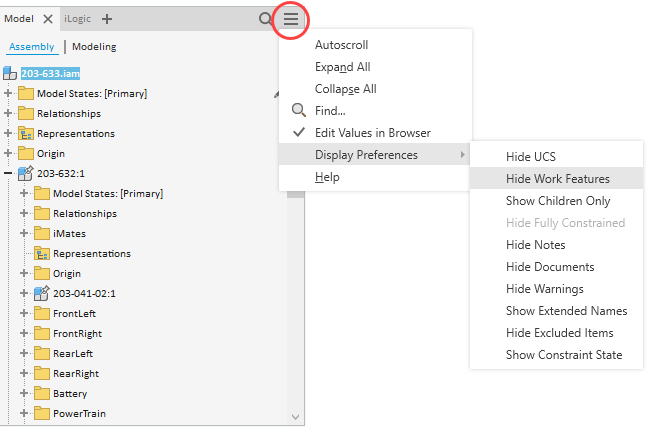
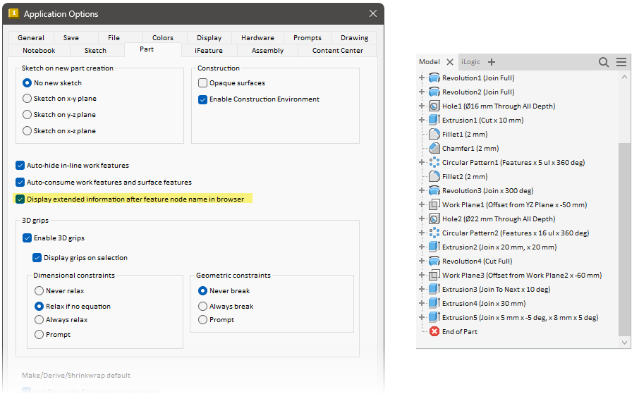
Enable Extended Information to add extra information about the feature or part. For example, with revolves it adds the output type and revolution angle to the feature name.
Working with parameters
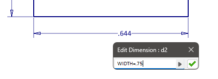
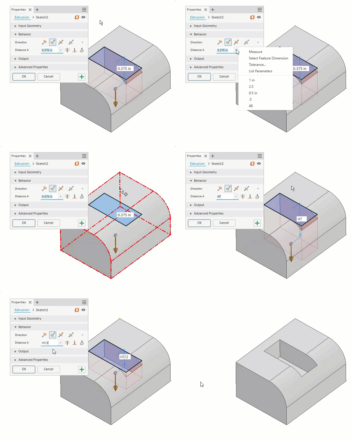
You can name a parameter on the fly by proceeding the value with the desired name and an equals (=). Yes, it’s that easy.
Want to use an existing dimension value or parameter but can’t remember its name? Just go and pick the dimension and Inventor extracts the parameter name for you.
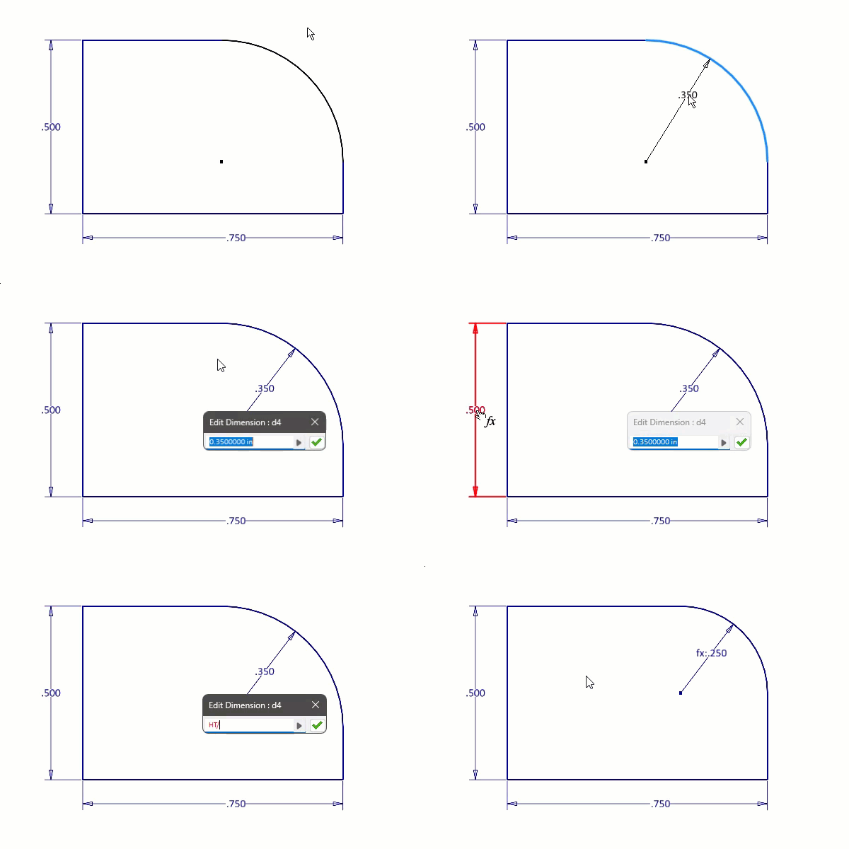
Can’t see the dimension? Use the right-click menu option Select Feature Dimension to pick the feature and reveal its dimensions.
Locking view representations
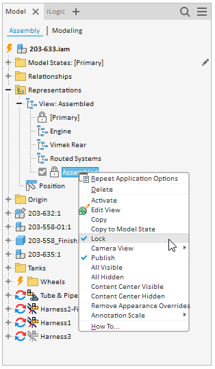
View Representations capture the appearance of your model, including what’s visible, what’s enabled, part colours, work feature visibility and more. They are live, so as you make changes Inventor automatically updates the active view rep to match.
However, locking a view representation freezes it so that changes to the view do not update the representation. This is useful when the view is used in things like drawings and you do not want it to change. You can make changes, like the appearance of a part, but those changes are not saved to the representation.
Editing model states with Excel
Use model states to build configurations of your assemblies and parts. As the model states become more involved, managing many features, consider editing the states via spreadsheet. You can then edit multiple states at one time.

Assembly tips for Autodesk Inventor
Placement options
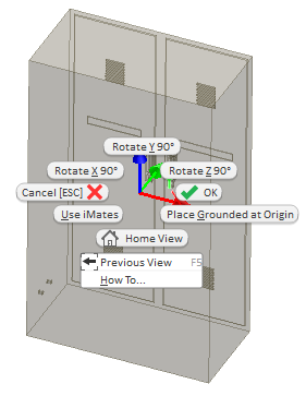
Inventor gives you options for rotating a component before placing it into an assembly. Right-click before selecting the insertion point and use the options to adjust the X, Y and Z orientation.
Drag and drop duplicate component
To quickly insert another instance of a component, drag it from the browser into the graphics window.
Save and replace
An assembly productivity tool, use Save and Replace to select a component, save a copy of it, and replace the selected instance with the new copy—all while maintaining the assembly constraints!
Isolate a part
Use Isolate, from the right click menu, to hide everything but the selected components. This is a great way to work on only what you want to work on.
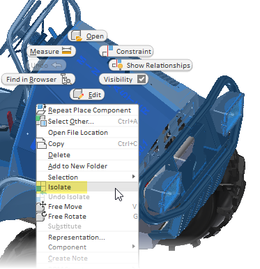
When ready, use Unisolate to return the display to its original condition.
Alt drag to constrain
Hold down the Alt key as you click-and-hold on a component near where you want to create a constraint (like an edge). Now drag the component where you want it constrained. The component snaps to preview the constraint, and when you release the left mouse button Inventor creates the constraint.
Flush for mate
It can be difficult to create Mate constraints when there are lots of faces and edges. To simplify the process, start with Flush instead. Flush only allows you to select faces—no edges, points or sketches— making your choice much easier. Then, before applying the constraint, flip back to mate.
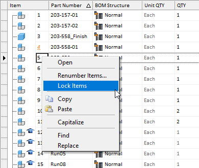
Locking BOM item numbers
In the Bill of Materials, lock an item to prevent it from changing in a renumber or other operation.
Drawing tips for Autodesk Inventor
Intersection dimensions
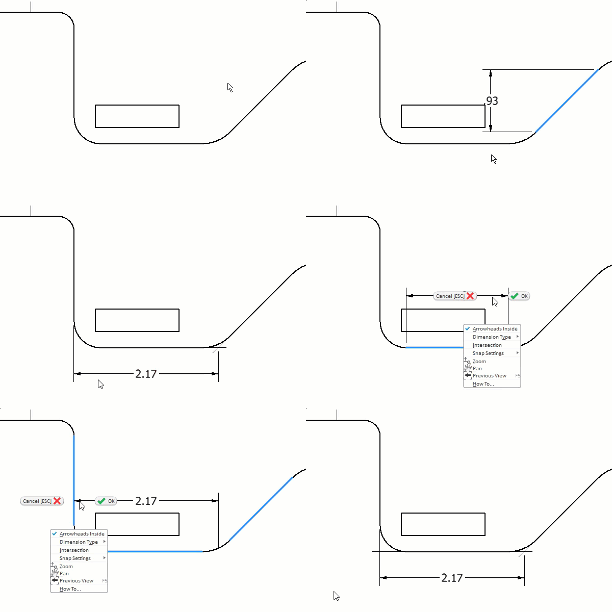
With a special workflow you can dimension to the intersection of where a sharp corner would be if not broken by a fillet, chamfer or other feature.
Start the dimension feature as normal and select first line to be dimensioned. Then right-click and select Intersection from the menu. As you hover over the second line Inventor previews the intersection. You can then left click to place the first extension line.
View associated notes
By design, text notes in Inventor are not associated to a view, meaning they stay in position even when the views change positions.
A workaround is adding a leader to place the text and associate it to a view with the leader. Even if you later remove the leader the text stays in position relative to the view.
Associate materials to hatch patterns
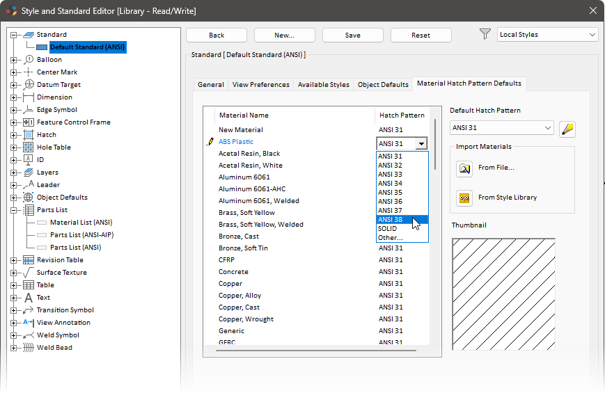
From the Style and Standard Editor, you can associate hatch patterns with specific materials. Then when creating section views Inventor assigns the correct hatch pattern based on the parts materials. Not only is this a great way to identify different materials in the view, but it’s also a great way to create standards across drawings.
