What to do after a feasible circuit simulation is built?
In our previous tutorial, How to Build a Hydraulic Circuit in Automation Studio, we looked at the most basic steps to build your simulation. In this tutorial, let’s show you how to use it.
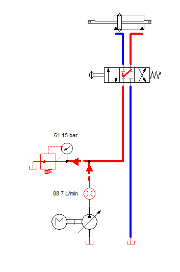
Let’s start with that same model with some minor modifications. First, change the cylinder from a single rod to a double rod style. Next, swap out the 4/2 directional control valve for a 4/3 valve with a closed center. This additional port allows for more exploration for the simulation operator. Namely, they can now set the circuit to be forward flowing, reverse flowing or without flow in the center.
Center configurations are sometimes used when multiple cylinder systems are being designed. They are known for slowing the buildup of heat and friction in the system. Hydraulic engineers and technicians with decades of experience often debate the need for a closed center versus a tandem center unit. For the sake of this simulation we are using a closed center because the component was easy to pull from the catalog.
The other additions to the circuit are a flow meter and a pressure gauge. Understanding the pressure and flow in your system is critical to optimizing the amount of energy you’re inputting versus what is output. Note that in this first image the flow meter is showing us a flow of 88 liters-per-minute and the gauge is showing pressure of 61.15 bar.
Once the circuit is built, what can we do with it?
When the circuit is built, and the model runs without errors, there are several design variables we can change to get the simulation closer to our real-life application. There are variables we can change while the simulation is running, such as the direction of the control valve, and variables we can only change when the simulation is stopped. For this circuit the easiest parameters to change are the pump displacement, the motor speed and the pressure relief valve’s cracking pressure.
Here in a pure design phase, simulations make it easy for us to move these parameters back and forth like imaginary levers to find the best possible configuration. In reality, however, we might be working with existing components. If so, tailor your simulation accordingly.
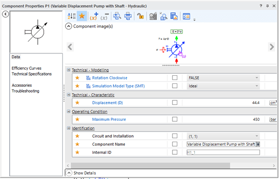
In a variable displacement pump, the parameter most likely to change in both build and simulation mode is its displacement. The pump likely has a range of displacements we can use to determine if it can create enough flow for our system. It also has an option to change its maximum pressure. When in simulation mode there’s a slider bar you can use to change the displacement. This is useful for a visualization of what happens to the flow and pressure while sliding the variable setting back and forth. However, if you are working with a specific displacement pump it makes sense to go into the component’s window and set the value manually.
The text is small, but within a component’s window Automation Studio gives users information about the math that goes into the parameters they set. For the displacement pump, you can make out a Q = D * ⍵ above the green arrow. This signifies that the flow rate is calculated by multiplying the pump’s displacement and the angular velocity. The equation T = Δp * D is also present. It signifies that the hydraulic pump’s torque is equal to the pressure change multiplied by the displacement. Having this information available is great, even if someone running a simulation calculation doesn’t need the it, the info is present without a search engine.
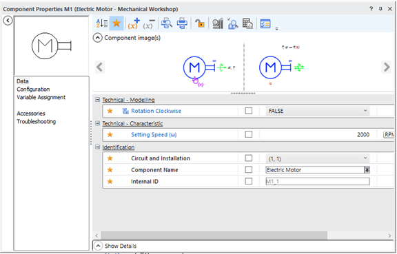
Opening the component window for the motor yields more information. The motor’s most important parameter is its speed, measured here in rotations per minute. It’s worth noting that the setting speed (⍵) shown would indicate that we’re working in angular velocity (or radians per second).
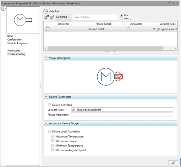
There’s a huge array of options available in these component windows. One that I like to show my students is the troubleshooting menu. This tab shows several of the major conditions where the motor would fail to work. This includes its maximum temperature, torque, angular speed and minimum temperature. These results could be helpful for someone trying to understand why a system isn’t working as planned, or as a first step toward figuring out the root cause of an issue. The troubleshooting tips from the component window here could also be useful for a quality engineer building a design failure mode effects analysis (DFMEA) to understand what might happen if the motor had issues.
The powerhouse of the circuit?
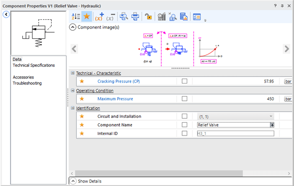
Another component that can be easily adjusted in our circuit is the pressure relief valve. The parameter can change while in run mode and build mode. It represents the pressure that is required by the system before the safety valve will open to let fluid through. Pressure relief valves are normally closed, signified in the diagram by the arrow indicating flow not being aligned with the lines that show the hose’s configurations. The diagram also shows a spring at the bottom of the valve that pushes it into this position until a sufficient cracking pressure is reached.
I teach my students that the working fluid is always going to take the path of least resistance, and the cracking pressure of the pressure relief valve will tell us how pressurized that path of least resistance can get.
This article talked about the three main components that control the hydraulic circuit, but many more options exist just in this simple study. The directional control valve, pressure gauge and flow meters are all customizable. We haven’t even touched the cylinder yet, which might be the most important component because the force outputted from the cylinder is probably why we’d start a simulation in the first place. Like many things in life, the more you learn about simulation the more you realize that there is left to learn.


