Everything you need to know to create smooth lofts with Inventor.
Lofting is a method in 3D CAD systems of building smooth transitions between multiple profiles. You use lofts to create organic, freeform shapes, like those found in consumer products or any time you need smooth transitions. Lofts can be simple shapes, like extrudes, but can also be more complex.
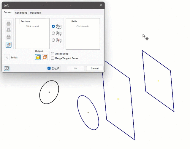
The basics
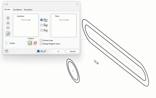
What do you need to build a loft? At least two profiles, which are called sections. These sections can be sketches, existing part faces, or a combination of both. The sections must be on different planes but do not need to be parallel. You can also loft to a point.
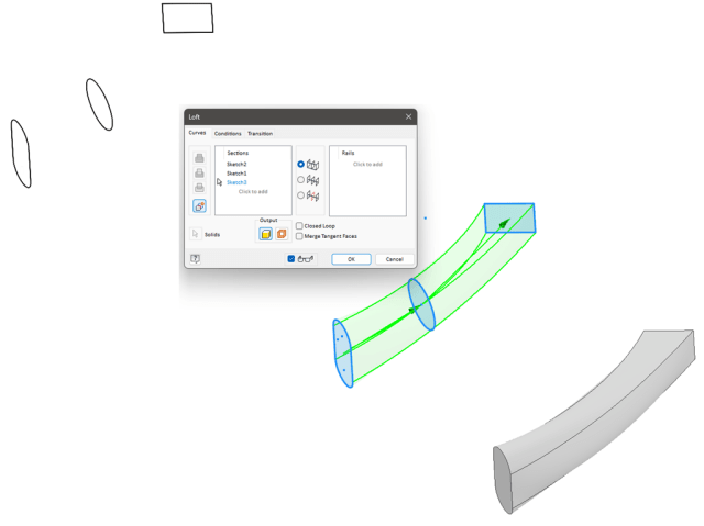
You want your sections in sequence, so the loft goes in one direction. If they are not in order, rearrange the sections by dragging and dropping in the Sections section. Hold Shift as you make selections to remove the section from the feature.
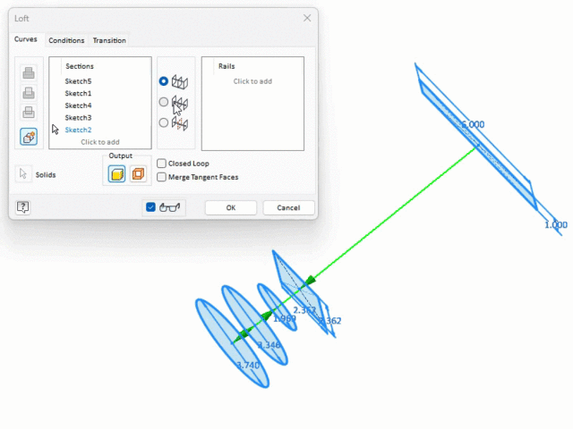
Pro Tip: Consistency leads to more robust models. Try to keep profiles compatible, as in having a similar number of points.
As with all Create Features, you can create the feature as a solid or surface. For solid lofts, select closed 2D or 3D sketch profiles or a closed face loop. For surface lofts, select open or closed sketch profiles or face loop of the part.
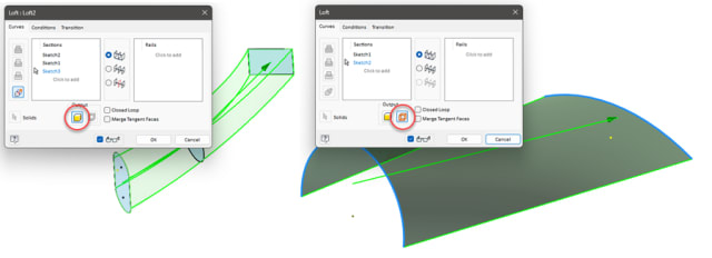
When multiple loops exist, you need to first select the face or sketch and then select the desired profile.
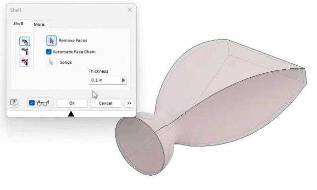
When you want a hollow body, as opposed to using a multi-loop profile, consider shelling the model instead.
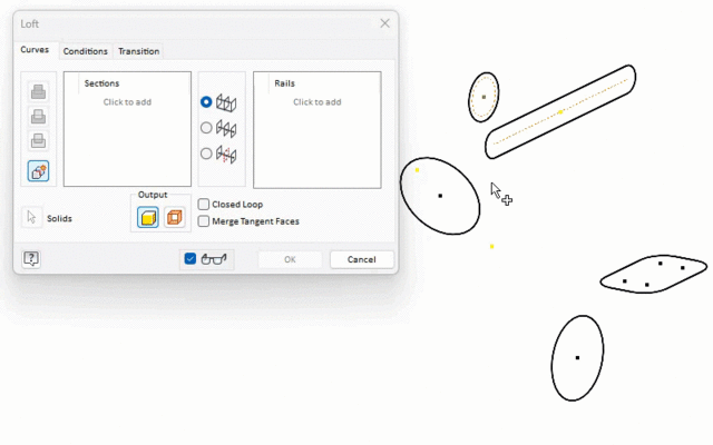
Select Closed Loop to join the first and last sections to loft a closed loop. Enable Merge Tangent Faces so that Inventor does not create an edge between tangent faces of the feature.
When the loft is the first feature, Inventor adds it as a new solid. When lofting is used as a secondary feature, you can add volume (Join), remove (Cut), or build intersections (Intersect).
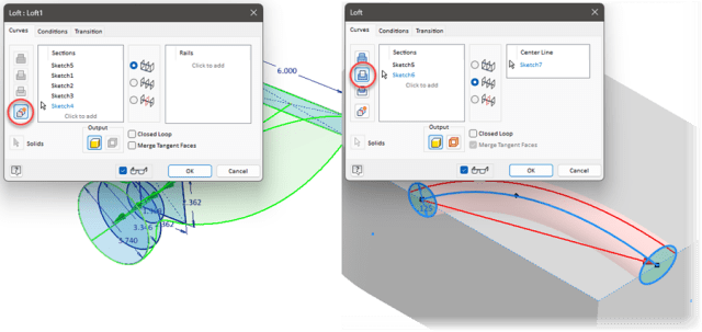
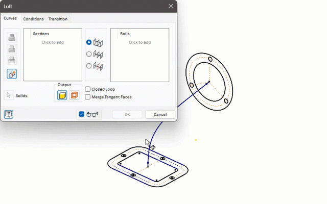
Rails (optionally) help manage how the sections connect, defining the direction and shape of the loft. The only restriction is the rails must intersect the sections.
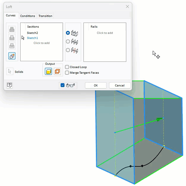
From the Curves tab, after you’ve selected the sections, click Rails. Then select the desired 2D or 3D curves.
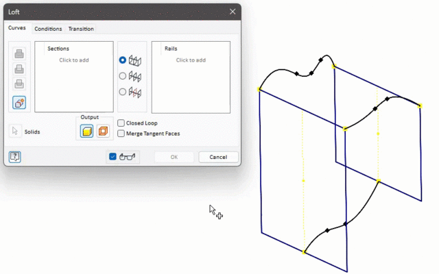
More lofts types
Centerline Lofts use a singular rail but use it in a sweep-like action, whereas a guide rail acts as a section, pulling the shape toward the profile, and the centerline holds the shape, ensuring it stays normal to the centerline between sections.
With Centerline Lofts, the sections follow the path instead of being pulled toward it.
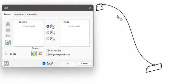
Pro Tip: When you want a natural smooth transition between sections, consider using centerline instead of rails, as it is typically easier to get the desired results.
An Area Loft is a Centerline loft but with more options. Area Lofts are useful when flow is important, or if you want to manage the cross-sectional area along the loft.
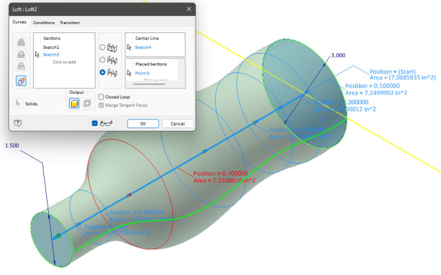
After selecting the centerline, dimensions appear at each section. Use these as a reference to review the area or to optionally override the section area with the desired value. When overriding the area, Inventor offsets the section uniformly.
You can insert sections along the centerline. These sections help define the cross-sectional area, managing the shape of the loft.
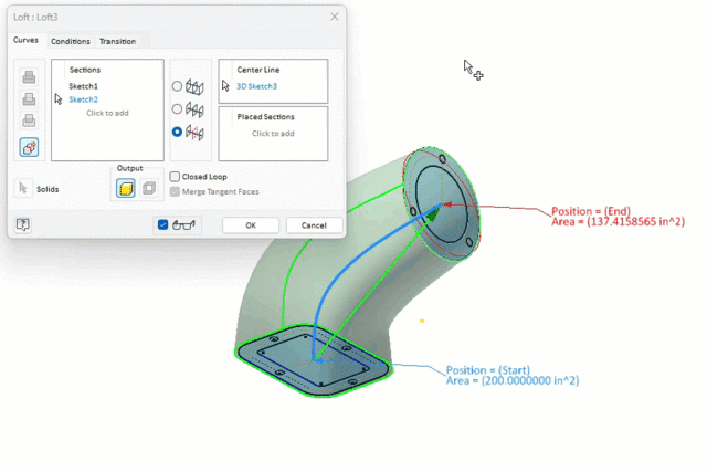
With added sections, you can set the position of the section along the centerline. Use Proportional to set the position (as a percentage) relative to the length of the centerline. Use Absolute to specify the exact distance along the centerline.

For the section area, set it specifically with the Area choice. You can alternatively set the area by a Scale Factor, which scales the section proportionally to the proceeding section.
Conditions
Because lofts can warp the surfaces they create, you set boundary conditions to keep curvature continuity and control the shape near its boundary.
From the Conditions tab, define conditions for end sections and outermost rails, select the condition from the list, and then specify the desired options. The available conditions are dependent on the loft, its sections, and the options selected. The default Free Condition applies no boundary conditions and allows Inventor to naturally transition the shape.
With 2D-sketched sections, in addition to the weight, you set the Angle. This angle is measured relative to the section plane.
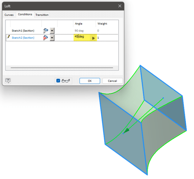
With most conditions, you set the weight. This unitless factor influences the condition. The higher the weight, the more the section shape extends before transitioning into the next shape. Be careful with the weight, as large values can cause twisting or self-intersecting faces.
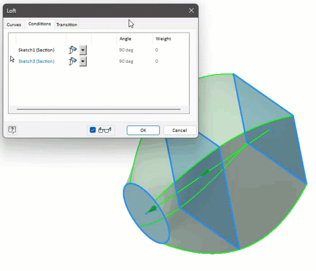
When the section (or rail) is next to a surface or when the section is a face, you can manage the curvature continuity. In these situations, the default Free condition is surface normal, meaning the surface is perpendicular to the edge or face.
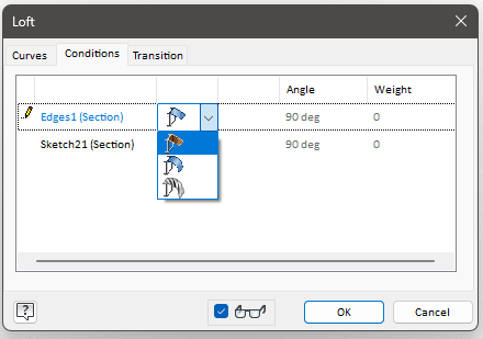
Tangent creates a G1 continuity. The surface normal matches along the meeting edges, like how fillets work.

Use Smooth to create G2 continuity. The amount of curvature matches along all meeting edges. This creates the smoothest transition between sections.
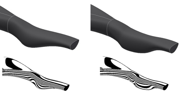
Use the flip toggle to change the direction the section moves away toward the next profile.
Points
To loft to a point, the point must be at the start or at the end of the loft.
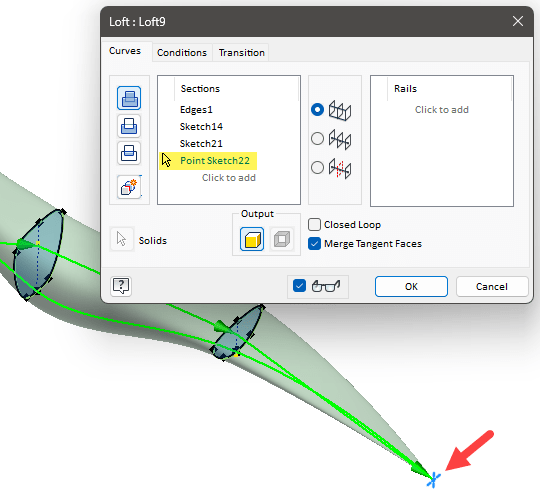
Use the Conditions tab to manage how the loft transitions into the point. The default is Sharp Point, meaning no condition is applied. Inventor transitions naturally, creating a pointed or cone-shaped tip on the feature.
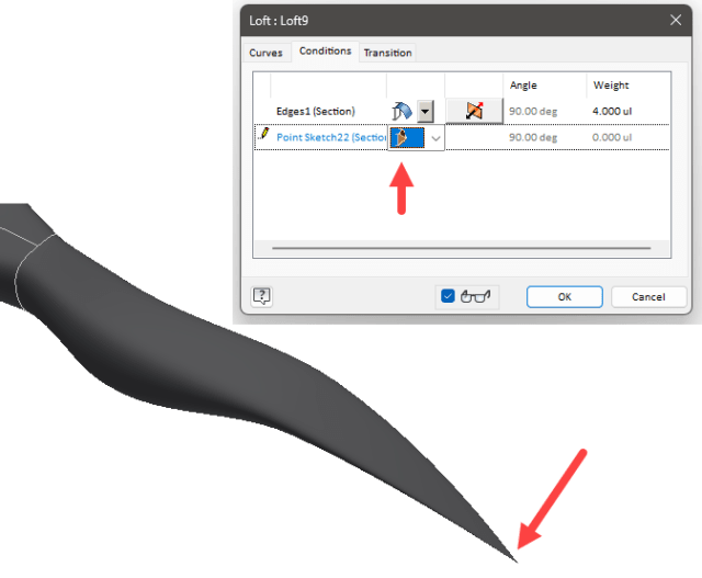
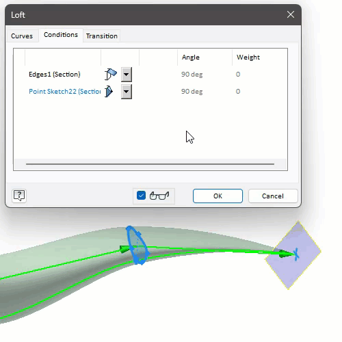
Select Tangent when you want the shape to transition into a rounded, dome-shaped point.
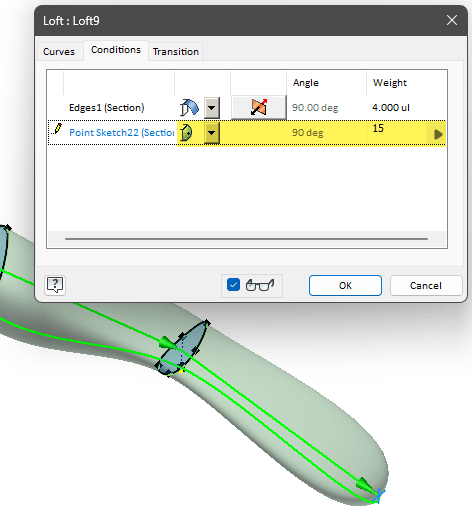
As the name applies, Tangent to Plane requires a work plane or a planar face. This condition applies tangency to the point using the selected plane for direction.
Transition
Inventor automatically maps the points, managing how one section transitions into the next. To change the mapping manually, uncheck Automatic Mapping.
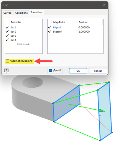
Point Sets are the calculated points, providing a connection from one section to the next. After selecting the Set in the dialog, you can select new point locations in the canvas. You are limited to selecting point locations along the existing section. Inventor snaps to endpoints, midpoints and other locations.
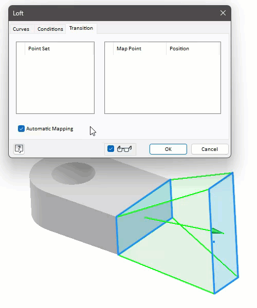
Inventor also lists the Map Point location in the dialog, highlighting the object type involved. You can adjust the Position, which is a percentage along the object (0 being one end, 0.5 in the middle, and 1 at the other end).
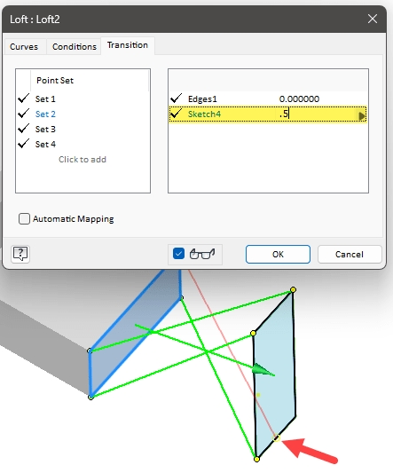
Select Click to insert another connection between sections. To remove a set, you need to select it in the dialog and press the Delete key.


