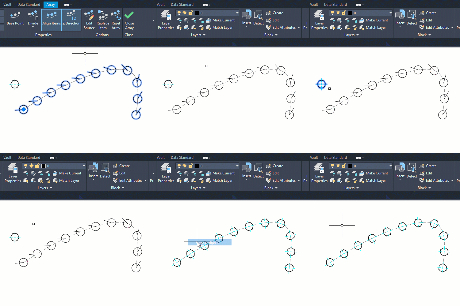
All about rectangular, polar and arrays along a path
The AutoCAD Array command creates multiple copies of selected objects arranged in a specific pattern. Its advantage is saving time over manually copying and positioning each object individually.
There are three types of arrays:
- Rectangular: patterns objects linearly in rows and columns
- Polar: patterns the objects radially about a selected center point.
- Path: evenly distributes the instances along a selected path.
Start the feature using the Array command.
The first step is to set the type. Or, if using the ribbon, start the feature by picking the array type. The main ribbon button is always the last-used type.
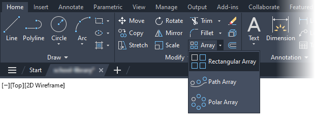
If you prefer the command line, you can also start a specific type using ARRAYRECT, ARRAYPOLAR and ARRAYPATH.
As with most commands in AutoCAD, you can start the command and then select the objects or you can select the objects and then start the command.
rectangular
A rectangular array is a pattern of objects dispersed linearly in rows and columns.
After starting the command and selecting the objects, the Array Creation contextual tab shows. Use this to set the number of rows and columns and the distance between the instances.
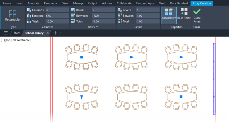
AutoCAD uses the current UCS (user coordinate system) to set the directions. Columns run in the X direction, while rows run along the Y direction. Use Levels when wanting to pattern in 3D to add instances in the Z direction.
The distance between instances is set as the distance Between or is based on the desired Total.
Use Between to set the distance between instances. It is easy to misunderstand the purpose. This is not the distance between instances. It is the distance between the base (starting) point of one instance and the base point of the next instance.
By using Total, you are setting the desired distance from the first instance’s base point to the base point of the last instance. AutoCAD divides this by the count to find the distance between instances.
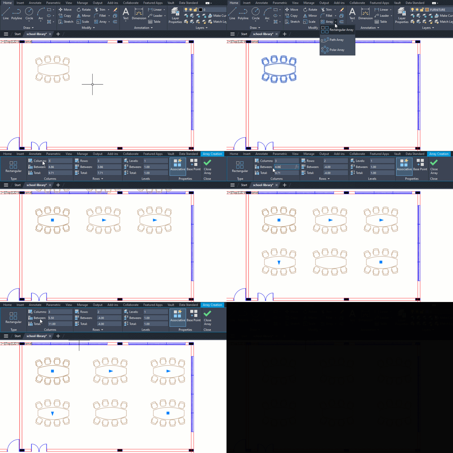
Use negative distances to have the array generate in the opposite direction.
Increment sets the increase (or decrease) in elevation for each row.
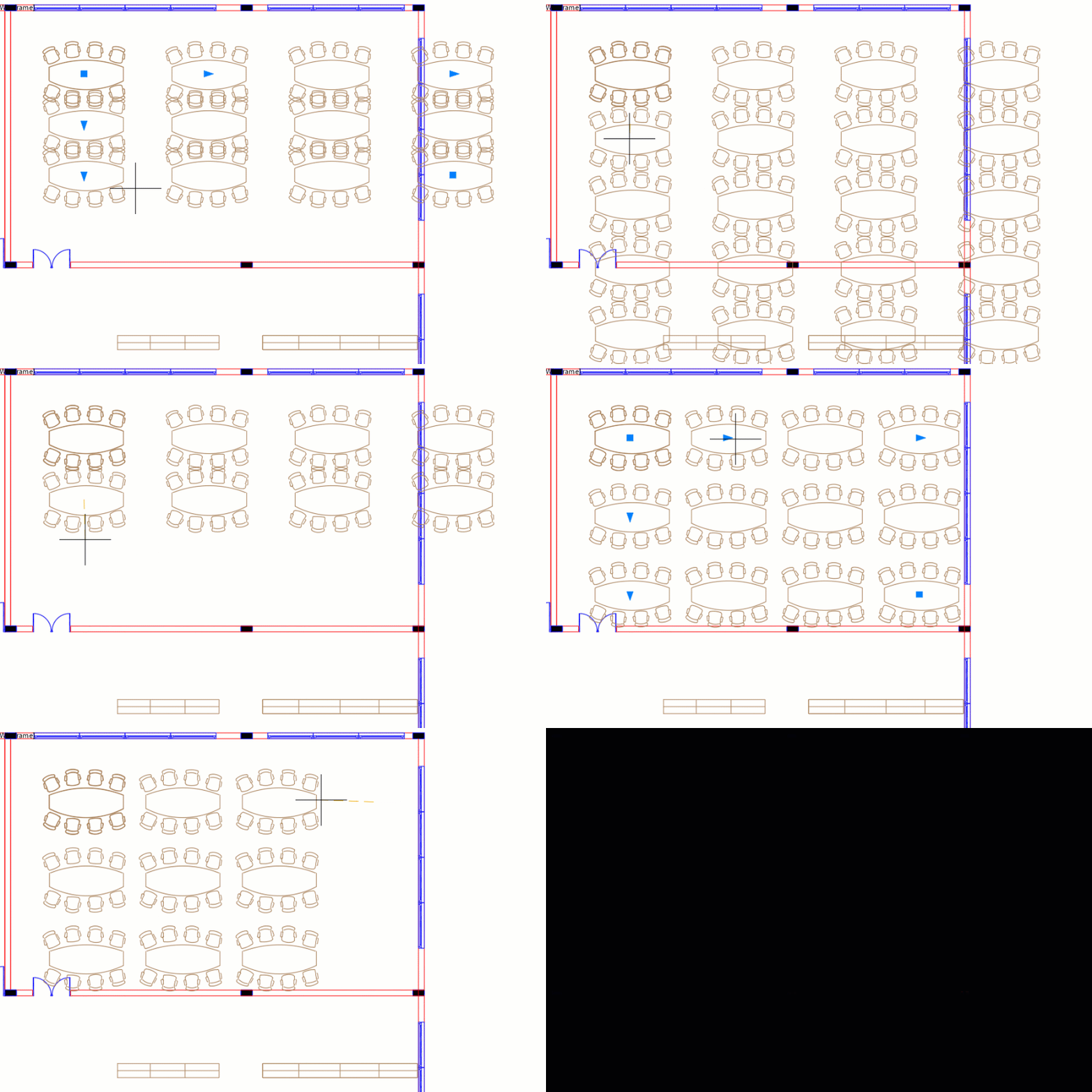
Instead of the ribbon, use grips to configure the array. Move the outer triangular grips to set the count and the inner ones to set the distance between them.
One of the square grips is for moving the array. The other is another method of setting the count, but in both directions.
Polar
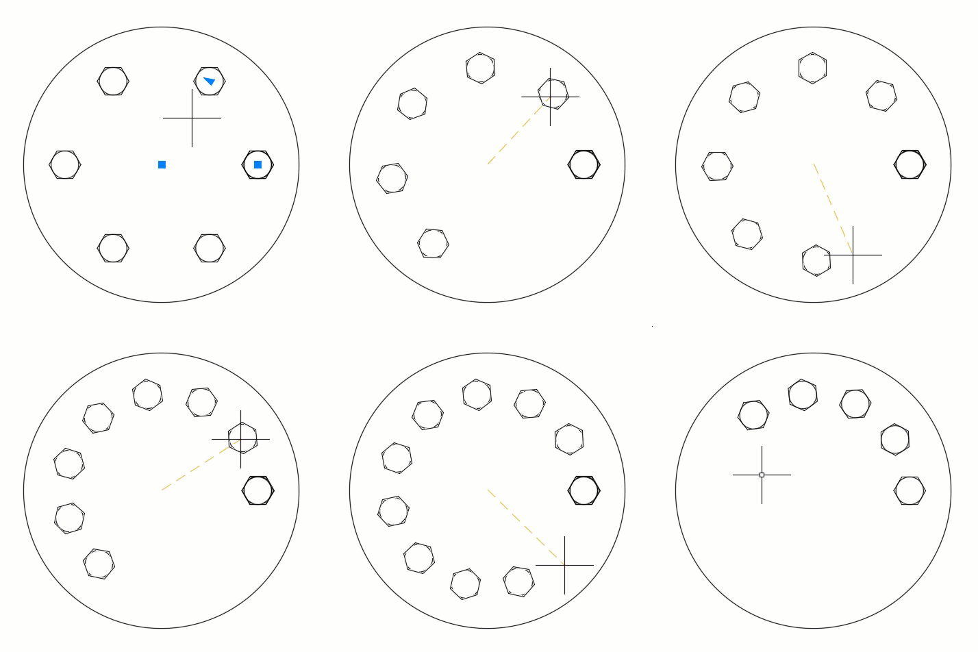
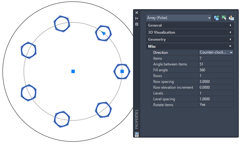
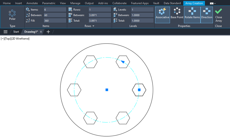
Use Polar to pattern the objects radially around a selected center point. You control the count (number of instances) and the angle between each instance.
Like with rectangular arrays, use Between to set the angle between each instance. The Fill is the total angle between the first and last instances base point-to-base point. AutoCAD divides this by the count to calculate the angle between each instance.
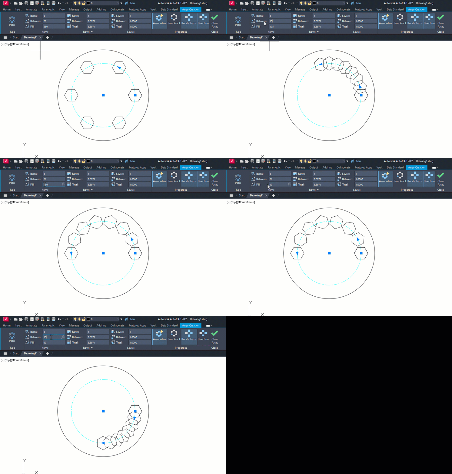
Select Direction to toggle the array direction – clockwise or counterclockwise.
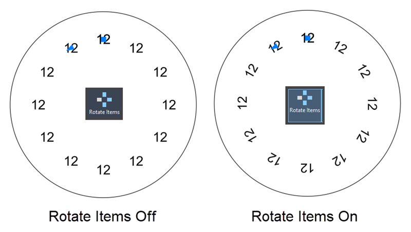
Toggle Rotate Items to set whether the objects rotate as they are arrayed.
Use the grips to dynamically adjust the array (as opposed to using the ribbon). In addition to changing the count and angle between instances, you can adjust the radius between the center point and the first instance.
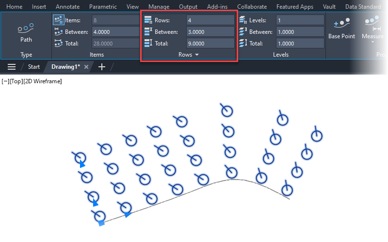
You can also array linearly while doing a polar array by setting the number of rows. Set the distance between each row instance or the total desired distance.
Editing an array
Associative arrays stay linked as a group. This allows you to alter the pattern after creation.
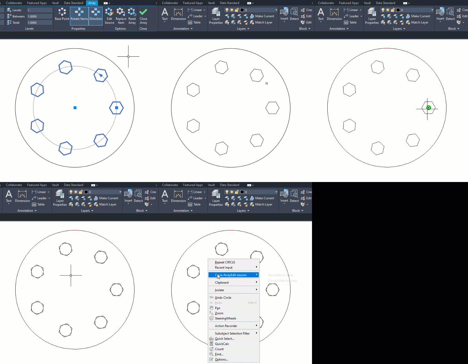
Like with blocks, you can change the original objects of an array. AutoCAD updates all instances automatically. To do this select the array and pick Edit Source from the ribbon. Then select the instance you want to change and make the changes. You can alter the geometry, remove objects and add new geometry. Do not forget to save changes when done.
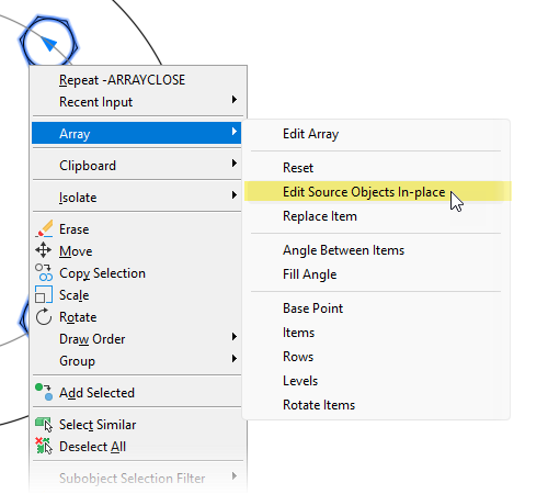
You can shortcut this process slightly using the right-click menu option.
You can adjust the array properties including the number of items and spacing. Use grips, the properties palette or the ribbon.
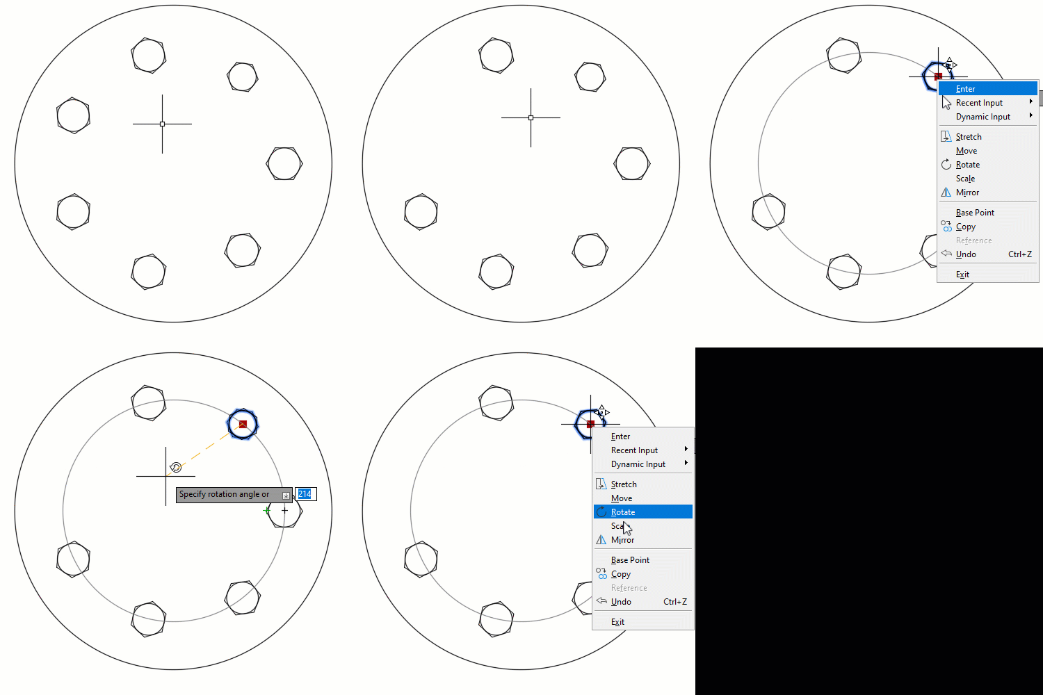
To modify just an instance within an associative array hold Ctrl as you select the instance. You can then move, rotate, scale, erase and perform other functions on it. Although now different than the other instances it continues to participate in the array.
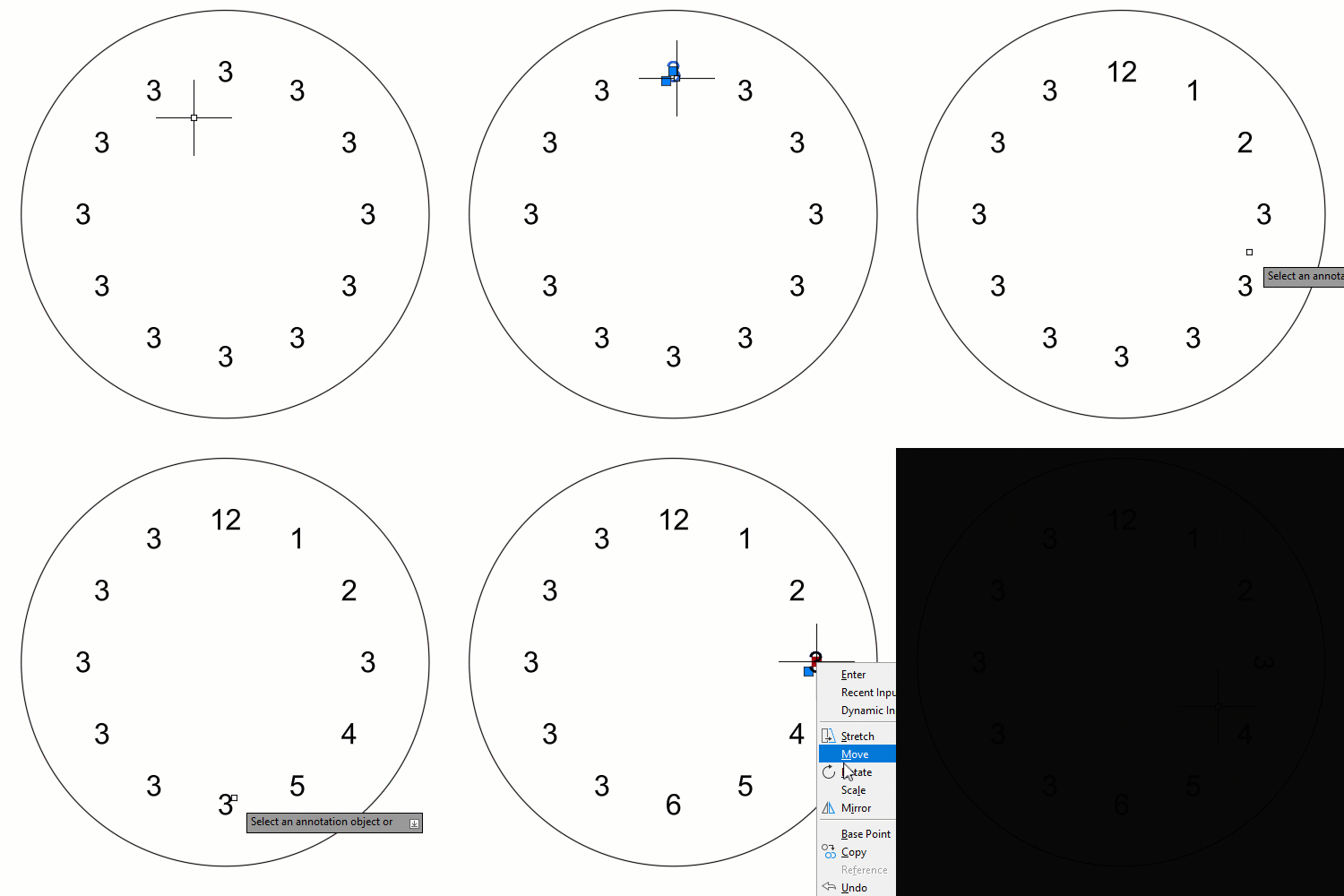
When creating an array use the option in the ribbon to make arrays non-associative. This creates a pattern of independent objects. It’s really a glorified copy. Changing one item has no effect on the other items.

Explode existing associative arrays when wanting a non-associative pattern.
Along a path
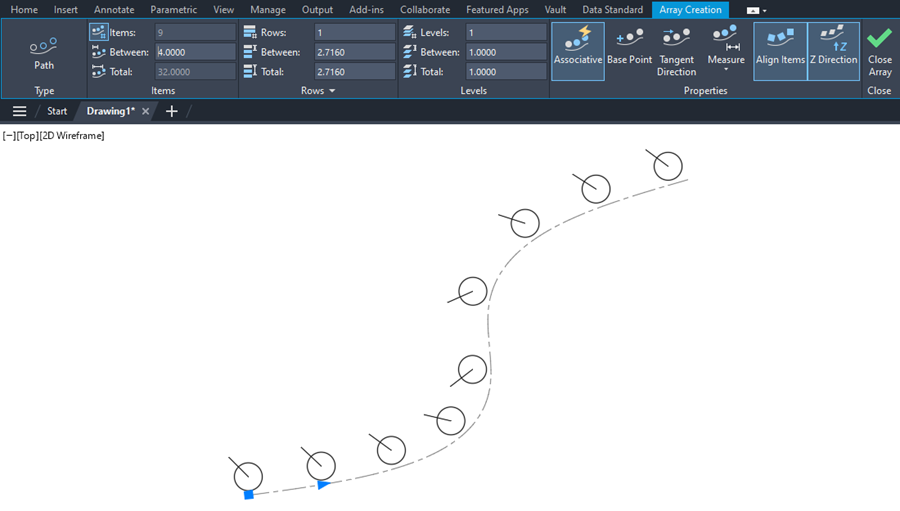
The Path array evenly distributes copies of selected objects along a selected path. Like with the other arrays you set the number of items.
You can only select one object for the path. But it can be a line, polyline, arc, spline, 3D polyline, helix or closed shapes like circles and ellipses.
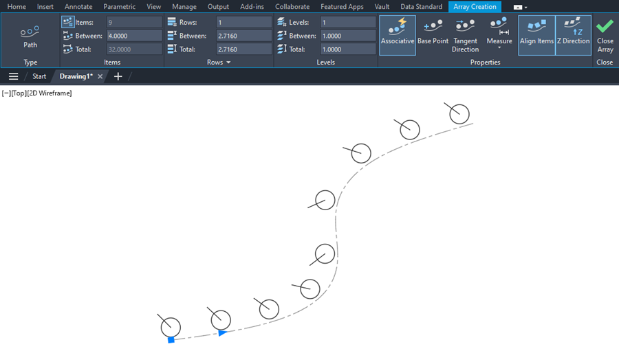
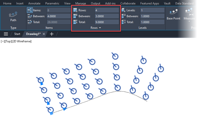
Like with polar arrays, you can also array linearly while arraying along the path. Set the desired number of rows and the distance between each row instance or the total desired distance.
Method sets how AutoCAD distributes the items along the path.
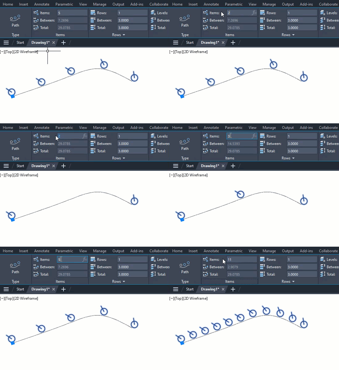
Divide spreads the items evenly along the length of the path so the distance between each instance is same. You do not set the distance as AutoCAD divides the path length by the number of instances to calculate the distance.
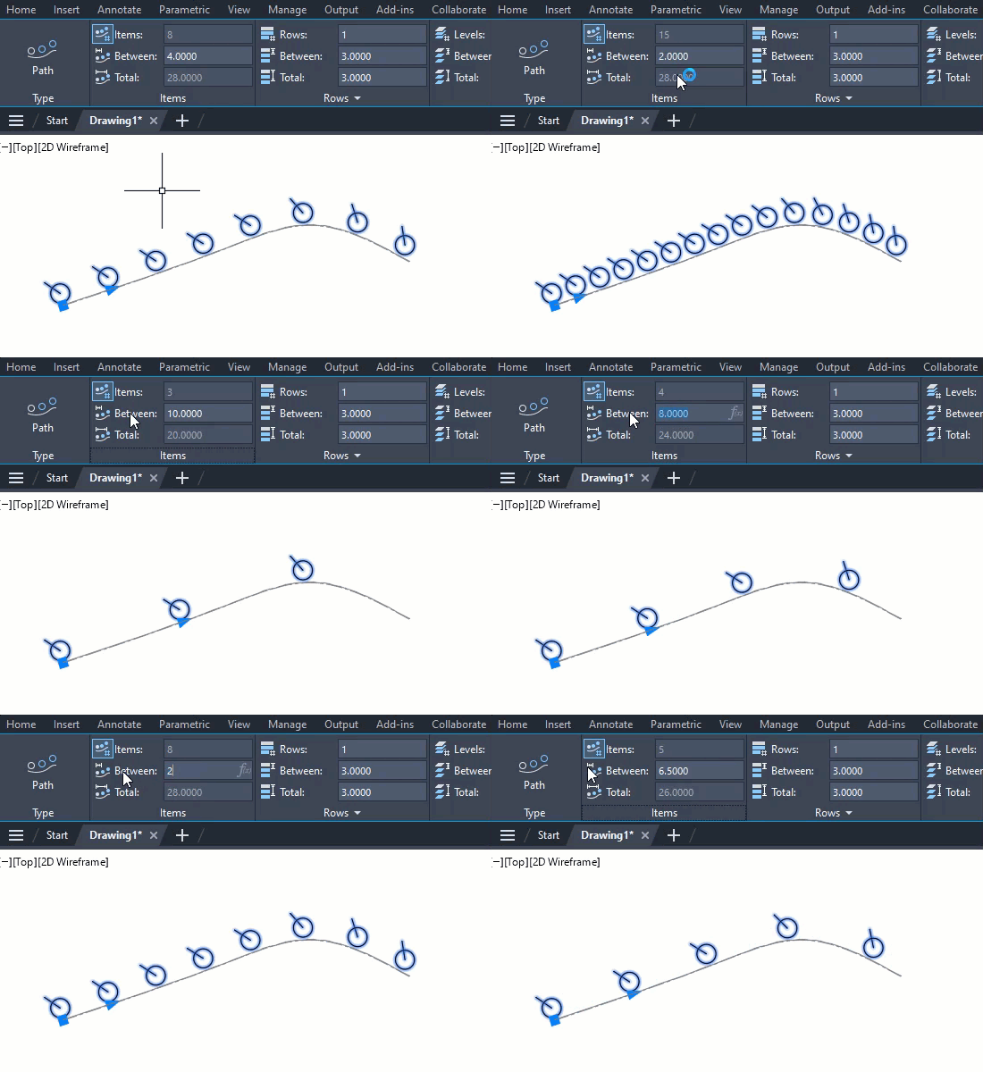
Measure distributes the items along the path at the specified distance. AutoCAD measures the distance along the path, not linearly like with rectangular arrays. AutoCAD continues to add instances until it gets to the end of the path.
Use Base Point to adjust the base point of the array. Or set the base point coordinates via the Properties palette. AutoCAD positions instances relative to the base point.
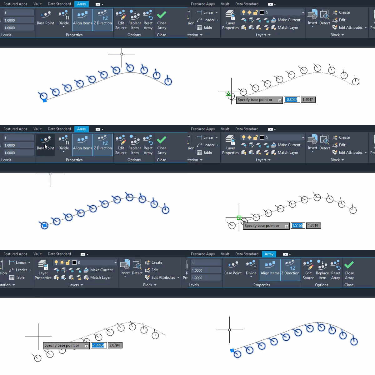
Set the base point as a key point to constrain the point to a location on the source objects. If you edit the source object, the base point stays coincident and updates in location with the source objects.

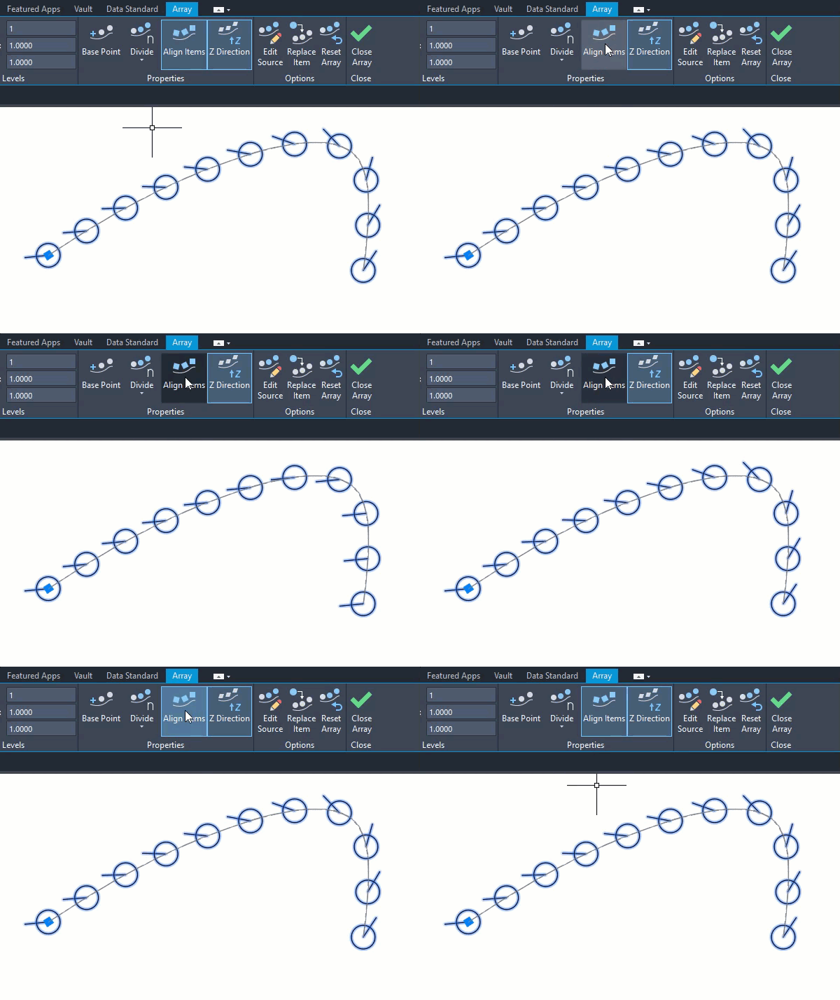
Use the tangent direction to set how the patterned items align relative to the starting direction of the path.
Enable Align items to line up each item tangent to the path direction relative to the first item’s orientation.
Replacing Items
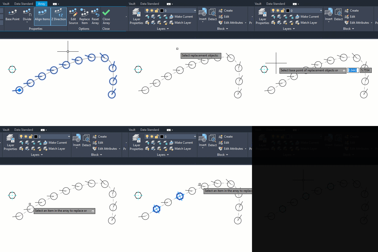
Use Replace Item when wanting to swap source objects for other objects in the drawing.
Start by selecting the replacement objects and the replacement objects base point. AutoCAD uses this selected base point as the insertion point for the objects into the array. Then select the array instances you want to replace. This creates an irregular array where not all the instances match.
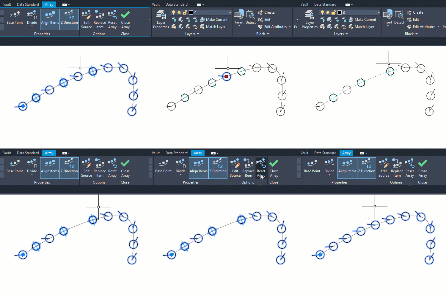
To restore the original objects and remove the overrides use Reset Array.
Alternatively, to replacing instances use the Source Objects feature to replace the original source objects, updating all instances in the array with the selected replacement objects.
